Timing device mechanism

A technology of initial position and impact bar, which is applied to the direction of time indication mechanical device, mechanically driven clock, and time indication by sound mode, which can solve the problems of height increase, acceleration, and structural space increase

Active Publication Date: 2017-06-27
LANGE UHREN
View PDF11 Cites 2 Cited by
  • Summary
  • Abstract
  • Description
  • Claims
  • Application Information

AI Technical Summary

Problems solved by technology

[0002] The problem with such striking mechanisms is that after the striking hammer hits the elastic sounding element, in particular the chime spring, the striking hammer bounces back due to the elasticity of the sounding element and accelerates again towards the sounding element
However, this requires increased force, with which the striker rod must be used to strike the striker against the sound-generating element, since the force of the spring element must also be overcome here.
This leads to an increase in the required installation space and negatively affects the impact of the striker on the sound emitting element due to the braking of the striker rod

Method used


Image

  • Timing device mechanism
  • Timing device mechanism
  • Timing device mechanism

Examples


Embodiment Construction

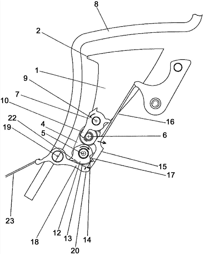
[0027] The illustrated striking mechanism for a reed watch has a striker lever 1 with a striker 2 at one end thereof. At its other end, the striker rod 1 is connected to the platform 4 at the screwed-in point 3 . At a distance parallel to the screwing point 3 , the platform 4 has a rotatably mounted hammer shaft 5 , with which the platform 4 is pivotably mounted and with which the striking rod 1 is pivotably mounted.

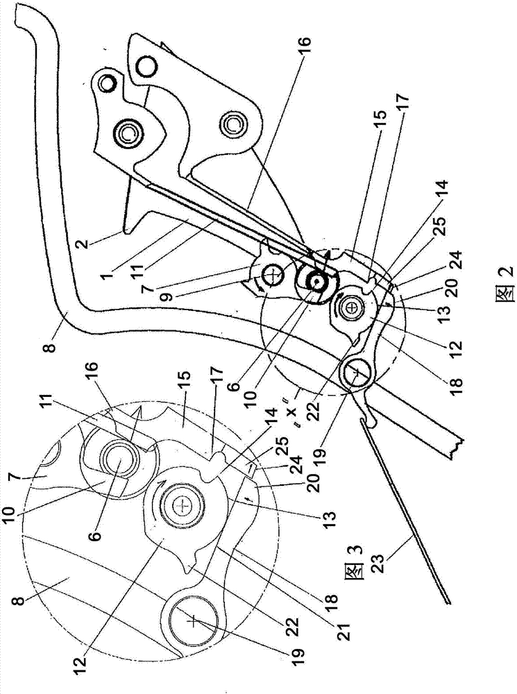
[0028] Coaxially with the tightening position 3, a follower pin 6 is arranged on the platform 4, and the motor 7 can drive it from the initial position ( figure 1 ) can be swiveled into the tensioned position (Figures 2 and 3). The starter 7 can be driven rotatably counterclockwise by a rake (not shown), such as a spring striking tool of a reed watch.

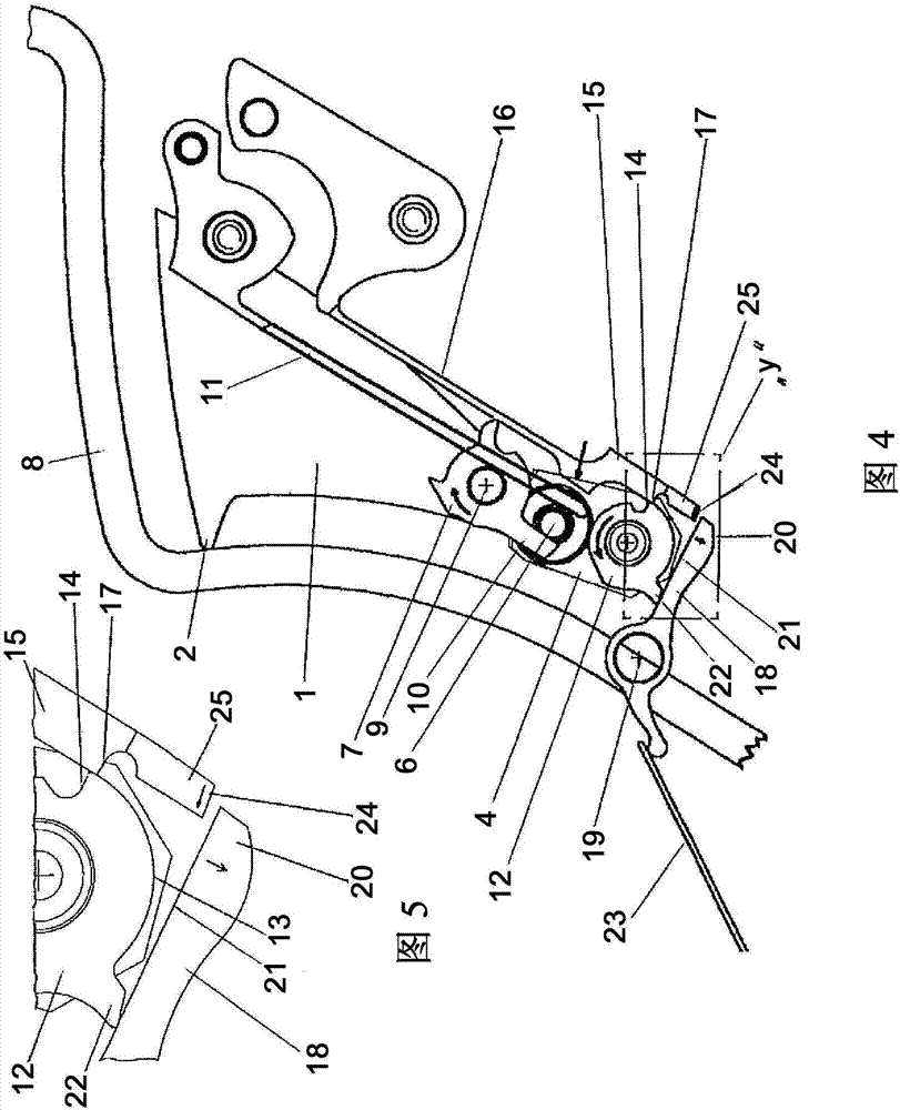
[0029] at the initial position ( figure 1 ) in the distance between the striking hammer 2 and the bell spring 8 is relatively small, and in the tensioned position (Fig. in the swing plane.

[0030] The actua...


PUM


Abstract

Timekeeping device of the invention relates to a watch, has an impact rod (1), it can swing around the axis swing supported at its end, and at the other end part from the oscillation axis with impact hammer (2), by the impact of elastic sound element. Then, the impact rod (1) against the elastic element near the sound from the initial position to swing away from the sound element tensioning position to be driven, and then through the elastic tension from the position after the initial position can swing to impact position, in which the impact hammer (2) hit in the sound element. From the impact location to the impact hammer (2) swing movement and sound element spaced in the closed position, the impact rod (1) by the locking device locking position in shape with the impact can be prevented from entering the locking position in the movement.

Description

technical field [0001] The invention relates to a striking mechanism for a timepiece with a striking lever which is mounted at its end so as to be pivotable about a pivot axis and which has a striking hammer at its other end facing away from the pivot axis, by which it can An impact-elastic sound-generating element, wherein the striker rod is driven pivotably against a spring force from an initial position near the sound-emitting element into a tensioned position away from the sound-emitting element, and can then be pivoted from the tensioned position through the initial position to In the striking position, in which the striking hammer strikes the sound-emitting element. Background technique [0002] The problem with such striking mechanisms is that after the striking hammer strikes the elastic sounding element, in particular the chime spring, the striking hammer bounces back due to the elasticity of the sounding element and is accelerated again towards the sounding element...

Claims


Application Information

Patent Timeline
Patent Type & Authority Applications(China)
IPC IPC(8): G04B21/06
CPCG04B21/06
Inventor 克里斯托夫·施伦克尔扬·文策尔托马斯·库纳特
Owner LANGE UHREN
Why Eureka
Try Eureka