Method, apparatus and system for recognizing knob operation

A technology of rotary operation and knob, which is applied in the direction of measuring devices, program control in sequence/logic controllers, instruments, etc., can solve the problems of misoperation of installation and disassembly of rotary buttons, and achieve the effect of solving misoperation and reducing misoperation

Pending Publication Date: 2017-06-27
GREE ELECTRIC APPLIANCES INC
View PDF6 Cites 0 Cited by
  • Summary
  • Abstract
  • Description
  • Claims
  • Application Information

AI Technical Summary

Problems solved by technology

[0005] Embodiments of the present invention provide a method, device and system for identifying the operation of the knob, so as to at least solve the technical problem of misoperation in the installation and disassembly process of the existing rotary button used to control electrical equipment

Method used


Image

  • Method, apparatus and system for recognizing knob operation
  • Method, apparatus and system for recognizing knob operation
  • Method, apparatus and system for recognizing knob operation

Examples


Embodiment 1

[0023] According to an embodiment of the present invention, there is provided an embodiment of a method for identifying the operation of a knob. It should be noted that the steps shown in the flowchart of the accompanying drawings can be executed in a computer system such as a set of computer-executable instructions, and, Although a logical sequence is shown in the flowchart, in some cases, the steps shown or described may be performed in a different order than here.

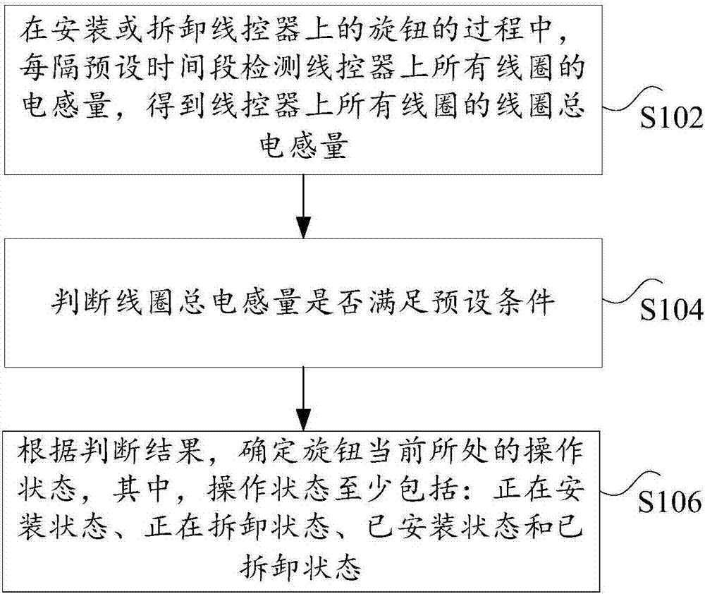
[0024] figure 1 It is a flowchart of a method for identifying the operation of a knob according to an embodiment of the present invention, such as figure 1 As shown, the method includes the following steps:

[0025] In step S102, in the process of installing or removing the knob on the wire controller, the inductances of all coils on the wire controller are detected every preset time period to obtain the total coil inductances of all coils on the wire controller.

[0026] Specifically, in the above steps, the installat...

Embodiment 2

[0090] According to an embodiment of the present invention, an embodiment of a device for identifying the operation of a knob is provided.

[0091] Figure 7 It is a schematic diagram of the structure of a device for identifying the operation of a knob according to an embodiment of the present invention, such as Figure 7 As shown, the device includes: an acquisition module 701, a first judgment module 703, and a first determination module 705.

[0092] The obtaining module 701 is used to detect the inductance of all coils on the wire controller every preset time period during the process of installing or removing the knob on the wire controller to obtain the total coil inductance of all coils on the wire controller.

[0093] Specifically, in the acquisition module 701, installation is to place the knob on the remote control panel; disassembly is to remove the knob from the remote control panel. The total inductance of the coil is the inductance of all induction coils on the knob. Th...

Embodiment 3

[0108] According to an embodiment of the present invention, an embodiment of a system for recognizing the operation of a knob is provided.

[0109] Figure 8 It is a schematic diagram of the system structure for identifying knob operation according to an embodiment of the present invention, such as Figure 8 As shown, the system includes: a wire controller 10, a processing unit 20, and a controller 30.

[0110] The wire controller 10 is used to detect the inductance of all coils on the wire controller every preset time period during the process of installing or removing the knob on the wire controller;

[0111] The processing unit 20, connected to the wire controller, is used to calculate the total inductance of all coils on the wire controller, and determine whether the total inductance of the coil meets the preset condition, and determine the current operating state of the knob according to the judgment result, where , The operating status includes at least: being installed, bein...


PUM


Abstract

The invention discloses a method, apparatus and system for recognizing knob operation. The method comprises the steps of: detecting the inductance values of all coils on a line remote controller at preset intervals during the installation or uninstallation of a knob on the line remote controller to obtain the total inductance value of all the coils on the line remote controller; determining whether or not the total inductance value of the coils satisfies a preset condition; determining the current operating state of the knob according to a determined result, wherein the operating states include at least an installing state, an uninstalling state, an installed state and an uninstalled state. The method, apparatus and system solve a technical problem that a knob for controlling appliance equipment may generate misoperation in the installation and uninstallation process in the prior art.

Description

Technical field [0001] The present invention relates to the technical field of electrical components, in particular to a method, device and system for identifying the operation of a knob. Background technique [0002] In this field, knobs are widely used in various electrical equipment as input devices for controlling switches and adjusting parameters of electrical equipment. [0003] A patent with the application number "201610591669.1" proposes an inductive knob wire controller, but during the installation and removal of the knob, the distance between the copper sheet on the knob and the wire controller coil changes, so the wire controller The change in coil inductance detected by the device may be incorrectly recognized as a knob rotation operation. [0004] In view of the above-mentioned problems, no effective solutions have yet been proposed. Summary of the invention [0005] The embodiments of the present invention provide a method, device and system for identifying the operat...

Claims


Application Information

Patent Timeline
Patent Type & Authority Applications(China)
IPC IPC(8): G05B19/04G01R27/26
CPCG05B19/04G01R27/26
Inventor 苏玉海贺小林唐杰叶铁英刘泉洲姚果袁健钟其他发明人请求不公开姓名
Owner GREE ELECTRIC APPLIANCES INC
Why Eureka
Try Eureka