Photosensitive device fixing structure and mobile terminal

A photosensitive device and a fixed structure technology, applied in the field of communication, can solve problems such as poor detection performance and large cumulative assembly tolerance, achieve the effects of shortening the size chain, reducing cumulative tolerance, improving detection performance and consistency of detection performance

Active Publication Date: 2017-06-27
VIVO MOBILE COMM CO LTD
View PDF6 Cites 0 Cited by
  • Summary
  • Abstract
  • Description
  • Claims
  • Application Information

AI Technical Summary

Problems solved by technology

[0005] Embodiments of the present invention provide a photosensitive device fixing structure and a mobile terminal to solve the problem of poor detection performance caused by the large cumulative tolerance of photosensitive device assembly in the prior art

Method used


Image

  • Photosensitive device fixing structure and mobile terminal
  • Photosensitive device fixing structure and mobile terminal
  • Photosensitive device fixing structure and mobile terminal

Examples


no. 1 example

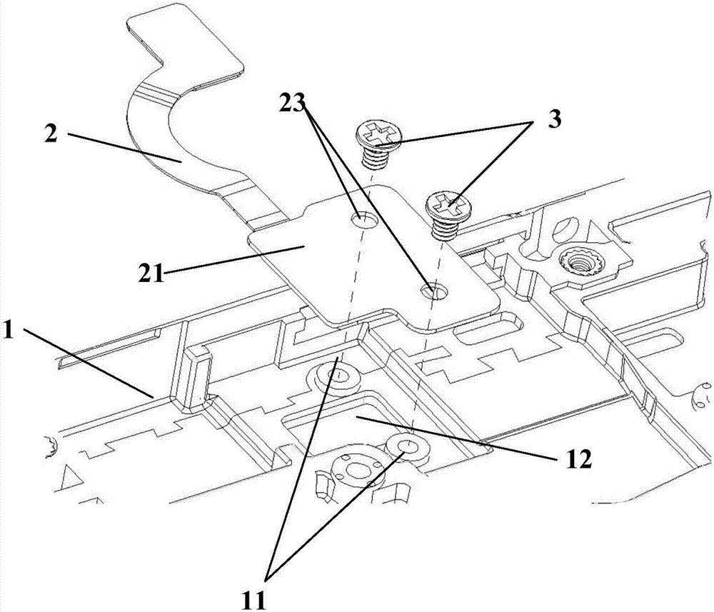
[0027] Such as figure 1 As shown, the embodiment of the present invention provides a kind of photosensitive device fixing structure, comprises: main board loam cake 1 and the flexible circuit board FPC assembly 2 that is fixed on the main board loam cake 1, wherein, FPC assembly is through BTB (Bdvanced Technology Bttachment) interface connected to the motherboard.

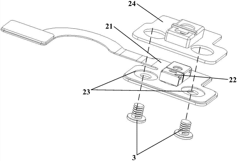
[0028] Specifically, such as Figure 1 to Figure 4 As shown, the FPC assembly 2 includes: a reinforcement board 21 , a photosensitive device 22 , a first positioning installation part 23 and a sealing sleeve 24 . Wherein, the FPC assembly 2 is fixed on the main board upper cover 1 through the first positioning installation part 23 .

[0029] Wherein, the reinforcing plate 21 is used to carry various electronic components in the FPC assembly 2, and is further contacted and connected with the main board cover 1, and the reinforcing plate 21 is generally a reinforcement for soldering components. The photosensitive...

no. 2 example

[0046] Such as Figure 5 Shown is a structural block diagram of a mobile terminal according to an embodiment of the present invention. Figure 5 The mobile terminal 500 shown includes a radio frequency (Radio Frequency, RF) circuit 510, a memory 520, an input unit 530, a display unit 540, a photosensitive device fixing structure 550, a processor 560, an audio circuit 570, a WiFi (Wireless Fidelity) module 580 and a power supply 590.

[0047] Wherein, the input unit 530 can be used for receiving number or character information input by the user, and generating signal input related to the user setting and function control of the mobile terminal 500 . Specifically, in the embodiment of the present invention, the input unit 530 may include a touch panel 531 . The touch panel 531, also referred to as a touch screen, can collect user's touch operations on or near it (such as the user's operation on the touch panel 531 using any suitable object or accessory such as a finger and a s...


PUM


Abstract

The invention discloses a photosensitive device fixing structure and a mobile terminal. The photosensitive device fixing structure comprises a mainboard upper cover and a FPC (Flexible Printed Circuit) assembly fixed to the mainboard upper cover, wherein the FPC assembly comprises a reinforcement plate, a photosensitive device directly fixed to the reinforcement plate, a first locating mounting part arranged on the reinforcement plate, and a seal sleeve arranged on the photosensitive device in a sleeving manner; and the FPC assembly is fixed to the mainboard upper cover through the locating mounting part. The FPC assembly of the mobile terminal is fixed to the mainboard upper cover, the photosensitive device is directly fixed to the reinforcement plate of the FPC assembly to serve as a part of the FPC assembly, and the FPC assembly can be fixed with the mainboard upper cover without a mounting bracket, so that a dimension chain of assembling of the photosensitive device is shortened; and an accumulated tolerance is reduced for improving the consistency of detection performance of the photosensitive device. In addition, the seal sleeve is arranged outside the photosensitive device in a sleeving manner, so that the mobile terminal has waterproof performance.

Description

technical field [0001] The invention relates to the technical field of communication, in particular to a fixed structure of a photosensitive device and a mobile terminal. Background technique [0002] With the rapid development of smart mobile terminals, smart phones have become a necessity in people's daily life. At the same time, high-frequency use puts forward higher requirements on the reliability of mobile phones, especially the waterproof performance of electronic devices. For example, in rainy days, humid environments, sweating during exercise, etc., electronic devices may lose their functions due to inflow of liquid. . [0003] Photosensitive devices are very important detection components on smartphones, and their assembly effect is of great significance to the overall performance of smartphones. In the prior art, the following two methods are often used for the assembly of the photosensitive device: Method 1. The photosensitive device is assembled on the main boa...

Claims


Application Information

Patent Timeline
Patent Type & Authority Applications(China)
IPC IPC(8): G06F1/16H04M1/02
CPCG06F1/1684H04M1/026
Inventor 祁进欧阳明华
Owner VIVO MOBILE COMM CO LTD
Why Eureka
Try Eureka