
Rotary seedling-transplanting hole-digging machine

A rotary and seedling transplanting technology, which is applied in the direction of excavation/covering trenches, application, planting methods, etc., can solve the problems of poor operation accuracy, different depths of soil holes, time-consuming and difficult processing, etc., to achieve mechanization, uniform depth and saving The effect of manpower and material resources

Inactive Publication Date: 2017-06-30
高新渠
View PDF7 Cites 0 Cited by
  • Summary
  • Abstract
  • Description
  • Claims
  • Application Information

AI Technical Summary

Problems solved by technology

In the prior art, there are two methods for digging holes in soil-moving cultivation. One is to use a hydraulically driven hole-digging machine installed on a tractor. However, this method is costly, and it will cause land for crops due to the rolling of the land by the tires of the tractor equipment. The ground is uneven, and the post-processing is time-consuming and difficult; one is to use manual digging, but relying on manpower to use tools to dig holes, the operator's operation is random, the operation accuracy is poor, and the error is large, resulting in different depths and distances of soil holes High strength, low efficiency, time-consuming and labor-intensive
Chinese patent 201210546078.4 discloses a hole-digging and spot-fertilizing machine, but it is mainly used for fertilizing crops, and the soil hole dug by it is relatively large, which is not suitable for transplanting seedlings and cultivation, and it cannot be used for seedling replenishment because it is a four-wheel machine as a whole. farmland

Method used


Image

  • Rotary seedling-transplanting hole-digging machine
  • Rotary seedling-transplanting hole-digging machine
  • Rotary seedling-transplanting hole-digging machine

Examples


Embodiment Construction

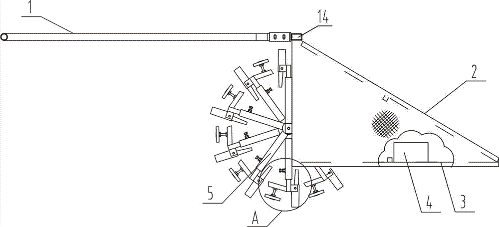
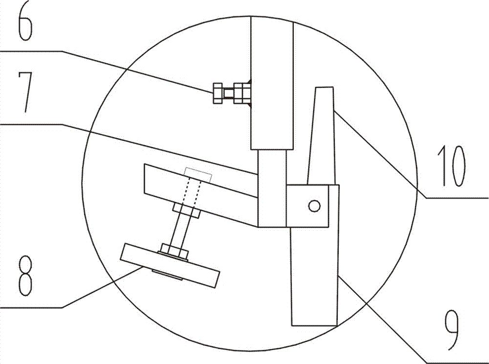
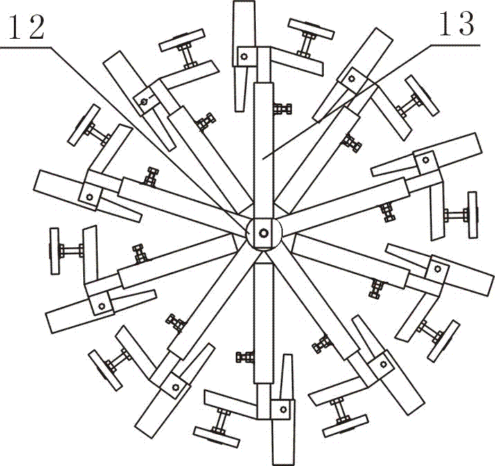
[0020] Now refer to the attached Figure 1-4 , combined with specific methods as follows:

[0021] The rotary seedling transplanting machine includes a handle 1, a main frame 3, a wheel body 5, a telescopic column foot 7, and a soil-taking sleeve 9. The main frame 3 is a frame structure, and the outer layer is covered with a protective shell Be protective cover 2, front end is little, and rear end is big, so that separate nursery stock, be provided with counterweight 4 at described main body frame 3 inner front end, described counterweight 4 can be bound on the main body frame 3, with The weight of the weight 4 can make the soil-taking sleeve 9 pressed into the ground; a hollow sleeve 14 is welded at the upper end of the rear part of the main frame 3, which can be penetrated through a transverse connecting rod to horizontally connect several main frames 3 , to realize a large-area opening hole; a horizontal shaft is welded near the rear end inside the main body frame 3, and a...


PUM


Abstract

A rotary seedling-transplanting hole-digging machine comprises a handgrip and a main rack. The main rack is a frame structure, which is externally coated with a protective shell. A transverse shaft is welded at the rear end inside the main rack. The transverse shaft passes through a wheel body, which is composed of a center bearing and back shafts. The back shafts are arranged on the outside of the center bearing. The back shafts are hollow and radiated at the outer side of the center bearing. The lower part of each back shaft is provided with a column base adjusting bolt. The lower end of each back shaft sleeves a telescopic column base, which is fixed by turning and tightening the column base adjusting bolt. The lower end of each telescopic column base is provided with a column base support. A soil sampling sleeve and a soil mass dialing piece are arranged at the opposite side of the corresponding column base support. The soil mass dialing piece is arranged on the telescopic column base at the side of the soil sampling sleeve. The Rotary seedling-transplanting hole-digging machine can rapidly dig soil holes and can control depth consistency of the soil holes and can make the spacing between crops to be equalized. In comparison with traditional manual hole-digging, the invention has the following advantages: manpower and material resources are saved.

Description

technical field [0001] The invention relates to agricultural planting machinery, in particular to a rotary seedling transplanting machine. Background technique [0002] In the seedling stage of crops, it is necessary to move the soil for cultivation, and to increase the yield of crops regularly through measures such as transplanting seedlings and filling seedlings. In the prior art, there are two methods for digging holes in soil-moving cultivation. One is to use a hydraulically driven hole-digging machine installed on a tractor. However, this method is costly, and it will cause land for crops due to the rolling of the land by the tires of the tractor equipment. The ground is uneven, and the post-processing is time-consuming and difficult; one is to use manual digging, but relying on manpower to use tools to dig holes, the operator's operation is random, the operation accuracy is poor, and the error is large, resulting in different depths and distances of soil holes High st...

Claims


Application Information

Patent Timeline
Patent Type & Authority Applications(China)
IPC IPC(8): A01C5/04
CPCA01C5/04
Inventor 高新渠
Owner 高新渠
Learn More