High-efficiency die cutting composite equipment

A composite equipment, high-efficiency technology, applied in the direction of lamination device, lamination auxiliary operation, lamination, etc., can solve the problems of low work efficiency, cost reduction, disadvantage, etc., achieve high motor utilization, enhance coordination, reduce The effect of labor costs

Inactive Publication Date: 2017-06-30
合肥钱锋特殊胶粘制品有限公司
View PDF4 Cites 0 Cited by
  • Summary
  • Abstract
  • Description
  • Claims
  • Application Information

AI Technical Summary

Problems solved by technology

The die-cutting and compounding equipment in the prior art has low working efficiency, and can only die-cut and compound one roll of products at a time, which is not conducive to reducing costs

Method used


Image

  • High-efficiency die cutting composite equipment
  • High-efficiency die cutting composite equipment
  • High-efficiency die cutting composite equipment

Examples


Embodiment Construction

[0026] The present invention will be further described below in conjunction with the accompanying drawings. The following examples are only used to illustrate the technical solution of the present invention more clearly, but not to limit the protection scope of the present invention.

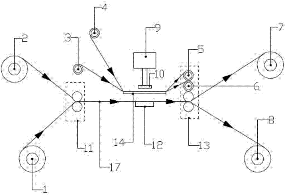
[0027] Such as figure 1 As shown, a high-efficiency die-cutting compound equipment includes a base material wheel, a carrier belt collection wheel, a material wheel, a finished product collection wheel, a material die-cutting mechanism, a base material die-cutting mechanism 11, and a fastening mechanism 13;

[0028] The material die-cutting mechanism is located between the carrier belt collecting wheel and the material wheel, and the carrier belt collecting wheel and the material wheel are all located between the base material die-cutting mechanism 11, the base material wheel, and the material wheel. Above the finished product collection wheel and the fastening mechanism 13, the base material w...


PUM


Abstract

The invention discloses high-efficiency die cutting composite equipment. The equipment comprises base material wheels, bearing belt collection wheels, material wheels, finished product collection wheels, a material die-cutting mechanism, a base material die-cutting mechanism and a fastening mechanism. Double channels are simultaneously machined through double rows of rollers, the production efficiency is improved, and the labor cost is reduced; the fastening mechanism is driven by one driving motor to rotate so as to drive the bearing belt collection wheels to move, power consumption is low, the motor utilization rate is high and the design is ingenious; the base material die-cutting mechanism is driven to rotate through gears, accordingly, the material die-cutting mechanism and the base material die-cutting mechanism synchronously move, the conventional situation that the base material die-cutting mechanism is driven to rotate through friction between a base material belt and the base material die-cutting mechanism is improved, inaccuracy of the die-cutting positions of cutting dies due to slipping of the base material die-cutting mechanism is avoided, and the coordination of the high-efficiency die cutting composition equipment is enhanced; the cutting dies are driven by cylinders to die-cut a material belt and compresses materials on a base material, and the equipment is simple in structure and convenient to maintain and monitor.

Description

technical field [0001] The invention relates to a high-efficiency die-cutting composite device, which belongs to the technical field of die-cutting composite mechanisms. Background technique [0002] Traditional die-cutting is a cutting process in the post-processing of printed matter. The die-cutting process can make printed matter or other paper products into a die-cutting knife plate for cutting according to the pre-designed graphics, so that the shape of the printed matter is no longer limited to Straight sides and right angles. Traditional die-cutting production uses a die-cutter to form a die-cutting plate according to the pattern required by the product design. Under the action of pressure, the printed matter or other plate-like blanks are rolled and cut into the required shape or cut. The die-cutting and compounding equipment in the prior art has low working efficiency, and can only die-cut and compound one roll of products each time, which is not conducive to cost ...

Claims


Application Information

Patent Timeline
IPC IPC(8): B32B37/00B32B38/04
CPCB32B37/0053B32B38/04B32B2038/045
Inventor 韩宝清
Owner 合肥钱锋特殊胶粘制品有限公司
Why Eureka
Try Eureka