Pressing pump

A technology of indenter and braces, which is applied in the field of pressing pump, can solve the problems of complexity, difficulty in processing half molds, and low processing efficiency.

Active Publication Date: 2017-06-30
丁要武
View PDF7 Cites 2 Cited by
  • Summary
  • Abstract
  • Description
  • Claims
  • Application Information

AI Technical Summary

Problems solved by technology

However, due to the reduction of parts, in order to ensure the function of the liquid pump, the structure of each part is designed to be more complicated, especially the structure of the piston rod, as shown in Figure 7a and 7b, its two diameters are larger, and the middle diameter is larger. Small, so it is necessary to make half molds during manufacture
The processing of Huff mold is difficult and the processing efficiency is not high, so the production efficiency of parts is always relatively low

Method used


Image

  • Pressing pump
  • Pressing pump
  • Pressing pump

Examples


Embodiment Construction

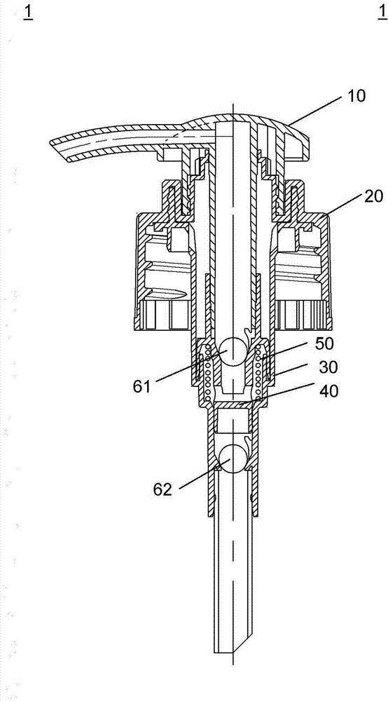
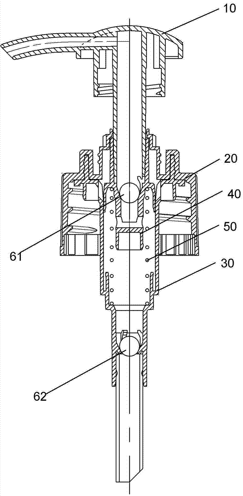
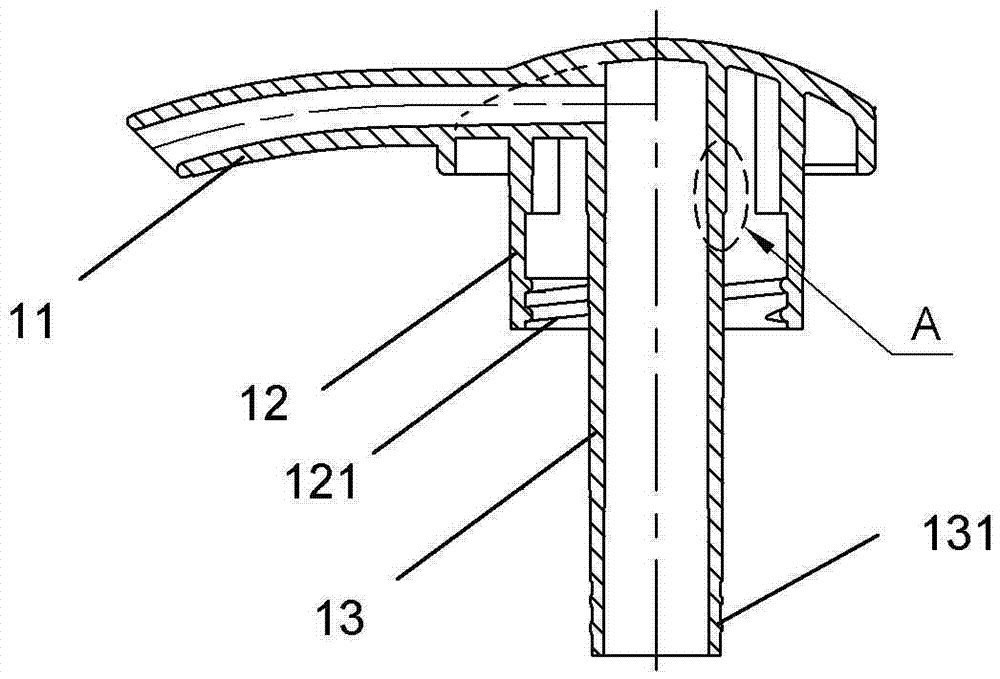
[0041] The following will be combined with Figures 1a-5b A specific embodiment of the present invention will be described in detail. It should be understood that what is shown in the drawings is only a preferred embodiment of the present invention, which is not intended to limit the scope of the present invention. Those skilled in the art can make various obvious modifications, variations and equivalent replacements to the present invention on the basis of the embodiments shown in the drawings, all of which fall within the protection scope of the present invention.

[0042] It should also be noted here that the words about direction such as "upper" and "lower" used herein are placed in a vertical orientation relative to the push pump (that is, the push pump is arranged so that its axis direction is opposite to the vertical direction). consistent) and determined.

[0043] like Figure 1a and 1b As shown, the compression pump 1 of the present invention includes a pressure he...


PUM


Abstract

The invention discloses a pressing pump. The pressing pump comprises an air cylinder, a threaded sleeve connected to the air cylinder, a pressing head and a piston connected to the lower portion of an inner ring, wherein the pressing head is provided with an outer ring and the inner ring, the inner ring extends downwards to the interior of the air cylinder, and the outer ring is connected with the threaded sleeve; the pressing head can move between a locking position and an unlocking position; in the locking position, the outer ring of the pressing head is fixed to the threaded sleeve, and in the unlocking position, the pressing head moves upwards, so that the outer ring is separated from the threaded sleeve, and the lower end of the inner ring still extends into the threaded sleeve or the air cylinder. The pressing pump is simple in structure, and all parts are easy to mold.

Description

technical field [0001] The invention relates to a pressing pump, in particular to a four-piece pressing pump. Background technique [0002] Traditional push-button liquid or lotion pumps typically consist of multiple parts. For example, Figures 6a and 6b show a push-type liquid pump 100 that is common on the market at present. The liquid pump includes a pressure head 110 and a piston rod 120 connected to the pressure head. It extends downward and enters the cylinder 130 , and a piston 140 is connected to the lower end of the piston rod 120 . The liquid pump 100 also includes a cylinder head 150 and a mouthpiece 160 . Cylinder head 150 is installed on cylinder 130, and is connected with tooth cover 160, and tooth cover 160 has internal thread, and this internal thread cooperates with the external thread of the container opening place that above-mentioned liquid pump is installed, thus liquid pump is installed in container superior. [0003] In addition to the main compone...

Claims


Application Information

Patent Timeline
Patent Type & Authority Applications(China)
IPC IPC(8): B65D47/34
CPCB05B11/1001B05B11/1047B05B11/106B05B11/0064
Inventor 丁要武
Owner 丁要武
Why Eureka
Try Eureka