
Patsnap Eureka
For R&D, Patsnap Eureka makes reading and utilizing patents & technical documents easy.
Patsnap Eureka AIR
Designed for self-driven R&D workflows. Generate viable solutions, solve complex R&D challenges, empower your innovation with AI.

Patsnap Eureka Materials
Designed for material experts only. Revolutionize your material R&D, from search, analyze, to developing new materials.

TechResearch
Generate reliable direction feasibility study reports for your R&D in just a few steps.

TechSeek
Discover and master advanced knowledge NOW. Basics, ideas, possibilities, all at once.

TechMind
As an expert in R&D Theories, TechMind can generates customized viable solutions instantly.

TechRisk
Analyze your overall solution with one click, know your potential R&D risks in advance.

TechMonitor
Get weekly tech updates, stay abreast of the latest tech innovations and key insights.
Assistant melting mechanism of cylinder dyeing machine
A dyeing machine and drum technology, applied in the field of drum dyeing machines, can solve the problems of high concentration and poor dilution effect, and achieve the effect of uniform addition and cost reduction
- Summary
- Abstract
- Description
- Claims
- Application Information
AI Technical Summary
Problems solved by technology
Method used
Image

Examples
Embodiment 1
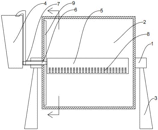
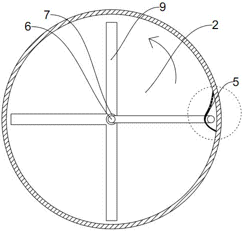
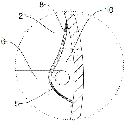
[0017] The auxiliaries and materials mechanism of a drum dyeing machine described in this embodiment includes a drum 2 and a frame 3. The drum 2 is connected to the frame 3 through a main shaft 1, and a liquid inlet is arranged axially in one of the main shafts 1. The pipe 6 and the liquid inlet pipe 6 extend from the outside of the drum 2 to the inside of the drum 2. The liquid inlet pipe 6 outside the drum 2 is connected with a chemical hopper 4, and a chemical material plate 5 is arranged on the circumferential side wall inside the drum 2. A closed cavity 10 is formed between the material plate 5 and the circumferential side wall of the drum 2, and the liquid inlet pipe 6 inside the drum 2 extends to the inside of the cavity 10. Taking the rotation direction of the drum 2 as a reference, when the drum 2 rotates The chemical material plate 5 at the front end of the direction is provided with some liquid outlet holes 8, and the nozzle of the liquid inlet pipe 6 in the cavity 1...
Embodiment 2
[0019] Such as figure 1 , figure 2 , image 3 As shown, the auxiliary material mechanism of a drum dyeing machine described in this embodiment includes a drum 2 and a frame 3, and the drum 2 is connected to the frame 3 through a main shaft 1, and is axially arranged in one of the main shafts 1 There is a liquid inlet pipe 6, and the liquid inlet pipe 6 extends from the outside of the drum 2 to the inside of the drum 2, the liquid inlet pipe 6 outside the drum 2 is connected to the chemical hopper 4, and the chemical material is arranged on the circumferential side wall inside the drum 2 A closed cavity 10 is formed between the plate 5, the material plate 5 and the axial side wall of the drum 2, and the liquid inlet pipe 6 inside the drum 2 extends to the inside of the cavity 10, taking the rotation direction of the drum 2 as a reference, in The chemical material plate 5 at the front end of the rotating direction of the drum 2 is provided with a plurality of liquid discharge...
PUM
 Abstract
Description
Claims
Application Information
 - R&D Engineer
- R&D Manager
- IP Professional
- Industry Leading Data Capabilities
- Powerful AI technology
- Patent DNA Extraction
Browse by: Latest US Patents, China's latest patents, Technical Efficacy Thesaurus, Application Domain, Technology Topic, Popular Technical Reports.
© 2024 PatSnap. All rights reserved.Legal|Privacy policy|Modern Slavery Act Transparency Statement|Sitemap|About US| Contact US: help@patsnap.com