

Charge Motion Control Valve Seal and Method of Assembly
A technology of seals and flapper valves, used in engine control, engine components, charging systems, etc., can solve problems such as inability to solve airflow, inability to solve the problem of sealing the expected flow path, etc.
- Summary
- Abstract
- Description
- Claims
- Application Information
AI Technical Summary
Problems solved by technology
Method used
Image

Examples
Embodiment Construction
[0017] As will be appreciated by persons of ordinary skill in the art, various features of an embodiment shown and described with reference to any one of the figures may be combined with features shown in one or more of the other figures to obtain a feature not shown and described in detail. other examples. The combinations of features shown provide representative embodiments for typical applications. However, various combinations and modifications of the features consistent with the teachings of this disclosure may be desired for a particular application or implementation. One of ordinary skill in the art may recognize similar applications or implementations, whether or not described or shown in detail.
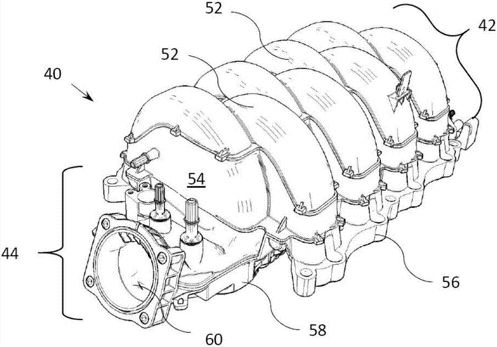
[0018] Intake manifold 40 in figure 1 shown in . The upper manifold section 42 has a top shell 52 connected to an upper middle shell 54 . In addition, the top shell 52 is integrally formed with the upper and middle shells 54 . The lower manifold 44 has a lower midshell ...
PUM
 Abstract
Description
Claims
Application Information