
Monitoring frame equipment

A kind of equipment and frame technology, applied in the field of monitoring equipment, can solve the problems of easy blind spots in the monitoring area and limited monitoring range

Pending Publication Date: 2017-06-30
安徽驿盟物流科技有限公司
View PDF9 Cites 0 Cited by
  • Summary
  • Abstract
  • Description
  • Claims
  • Application Information

AI Technical Summary

Problems solved by technology

[0004] The purpose of the present invention is to provide a monitoring rack device, which solves the problem that traditional monitoring cameras are often fixed on walls or columns through mounting brackets. Due to the limitations of the traditional monitoring camera's own structure, its monitoring range is limited, and blind spots are prone to appear in its monitoring area. The problem

Method used


Image

  • Monitoring frame equipment
  • Monitoring frame equipment

Examples


Embodiment Construction

[0025] Specific embodiments of the present invention will be described in detail below in conjunction with the accompanying drawings. It should be understood that the specific embodiments described here are only used to illustrate and explain the present invention, and are not intended to limit the present invention.

[0026] In the present invention, unless stated otherwise, the orientation words included in the term such as "horizontal direction, vertical direction" only represent the orientation of the term in the normal use state, or are understood by those skilled in the art colloquially and should not be construed as a limitation of the term.

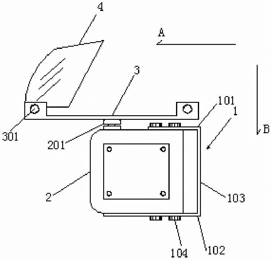
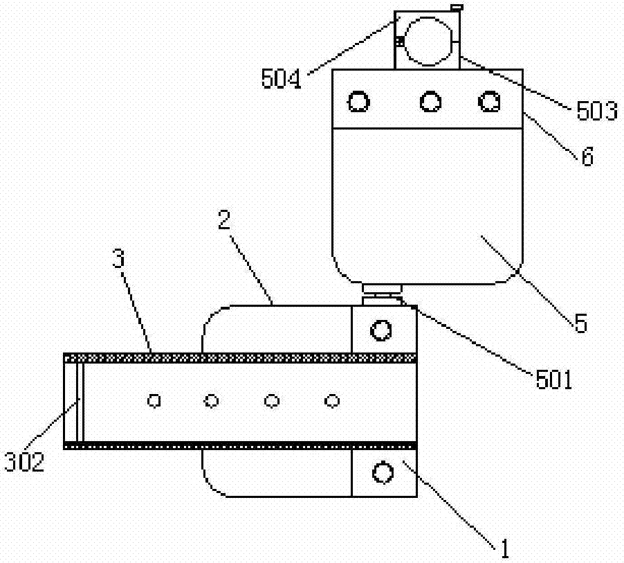
[0027] Such as figure 1 with figure 2 As shown: the present invention provides a monitoring frame equipment, the monitoring frame equipment includes a first frame body 1, a first rotating steering gear 2 is fixed on the first frame body 1, and the first rotating steering gear 2 The first rotating head 201 is fixed with a mount...


PUM


Abstract

The invention discloses monitoring frame equipment. The monitoring frame equipment comprises a first frame body, the first frame body is fixedly provided with a first rotary steering gear, and a first rotating head of the first rotary steering gear is fixedly provided with an installation plate arranged in the horizontal direction so that the first rotary steering gear can drive the installation plate to rotate in the horizontal direction; and the monitoring frame equipment furthermore comprises a second rotary steering gear fixed to a second frame body, and a second rotating head of the second rotary steering gear is connected with the first frame body so that the second rotary steering gear can drive the first frame body to rotate in the vertical direction. By means of the monitoring frame equipment, the problems that a traditional monitoring camera is usually fixed to a wall or a stand column through an installation bracket, due to limitation of the structure of the traditional monitoring camera, the monitoring range of the traditional monitoring camera is limited, and blind points occur easily in the monitoring area of the traditional monitoring camera.

Description

technical field [0001] The invention relates to the field of monitoring equipment, in particular to monitoring rack equipment. Background technique [0002] Surveillance camera is a semiconductor imaging device, which has the advantages of high sensitivity, anti-glare, small distortion, small size, long life, and anti-vibration. In the surveillance camera security system, the image generation is mainly from the CCD camera at present, and the stored charge can also be taken out to change the voltage. It has the characteristics of anti-vibration and impact and is widely used. Traditional surveillance cameras are often fixed on walls or columns through mounting brackets. Due to the limitations of the traditional surveillance camera's own structure, its monitoring range is limited, and blind spots are prone to appear in its monitoring area. [0003] Therefore, it is an urgent problem to be solved in the present invention to provide a monitoring rack device capable of increasing...

Claims


Application Information

Patent Timeline
IPC IPC(8): F16M13/02F16M11/12F16M11/18H04N7/18
CPCH04N7/18F16M11/121F16M11/18F16M13/02
Inventor 孔庆广史官清王配军安建民
Owner 安徽驿盟物流科技有限公司
Learn More