Point target space distance measurement positioning device and method

A technology of positioning device and point target, which is applied to measurement devices, distance measurement, line-of-sight measurement, etc., can solve the problem of inability to achieve distance measurement, and achieve the effect of reducing the difficulty of calculation

Inactive Publication Date: 2017-06-30
王磊
View PDF3 Cites 4 Cited by
  • Summary
  • Abstract
  • Description
  • Claims
  • Application Information

AI Technical Summary

Problems solved by technology

At present, there are also improvements to the laser scanning positioning technology. For example, using a V-shaped laser beam to replace a plane laser beam can realize direction findin

Method used


Image

  • Point target space distance measurement positioning device and method
  • Point target space distance measurement positioning device and method
  • Point target space distance measurement positioning device and method

Examples


example 1

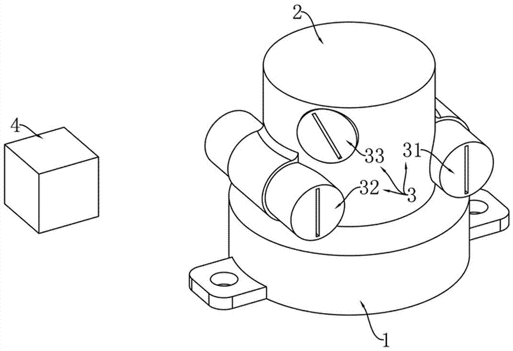
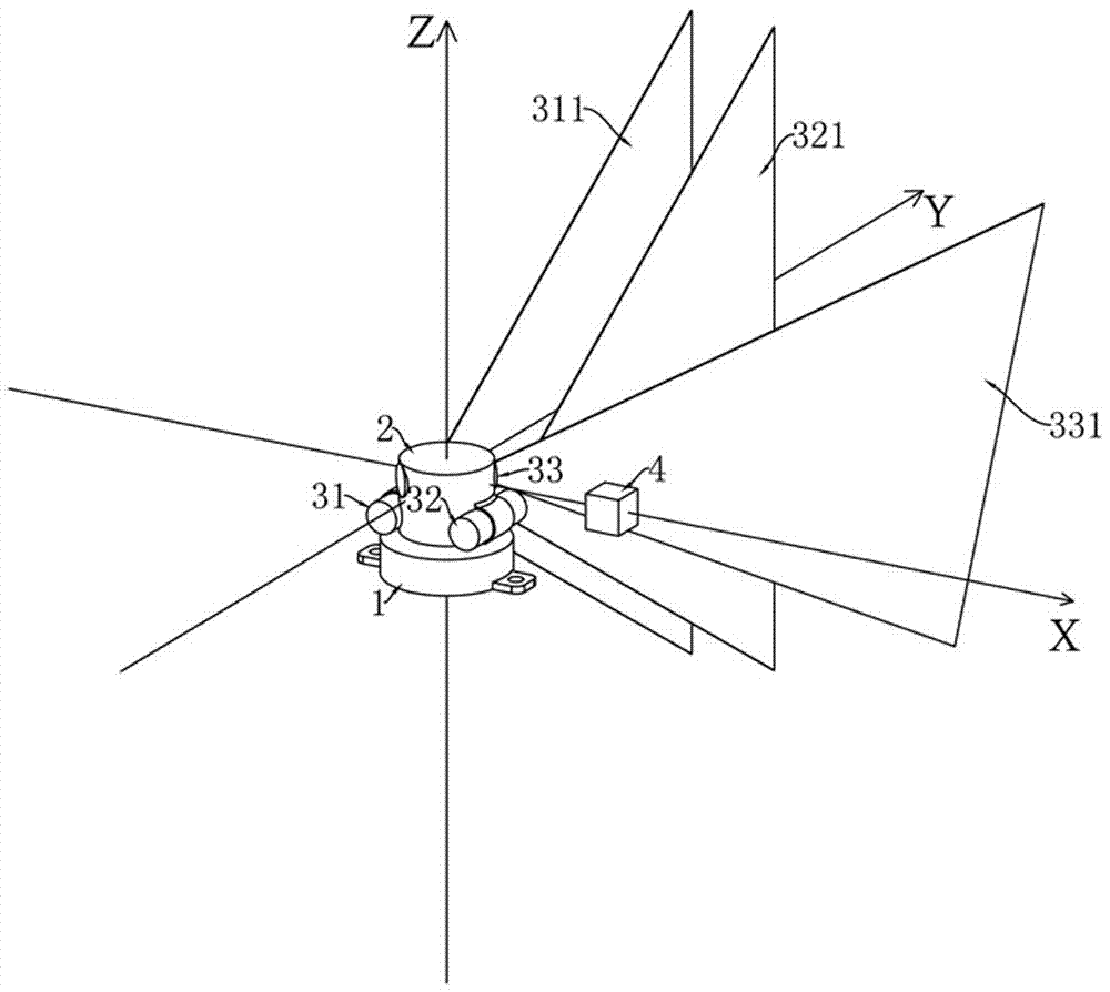
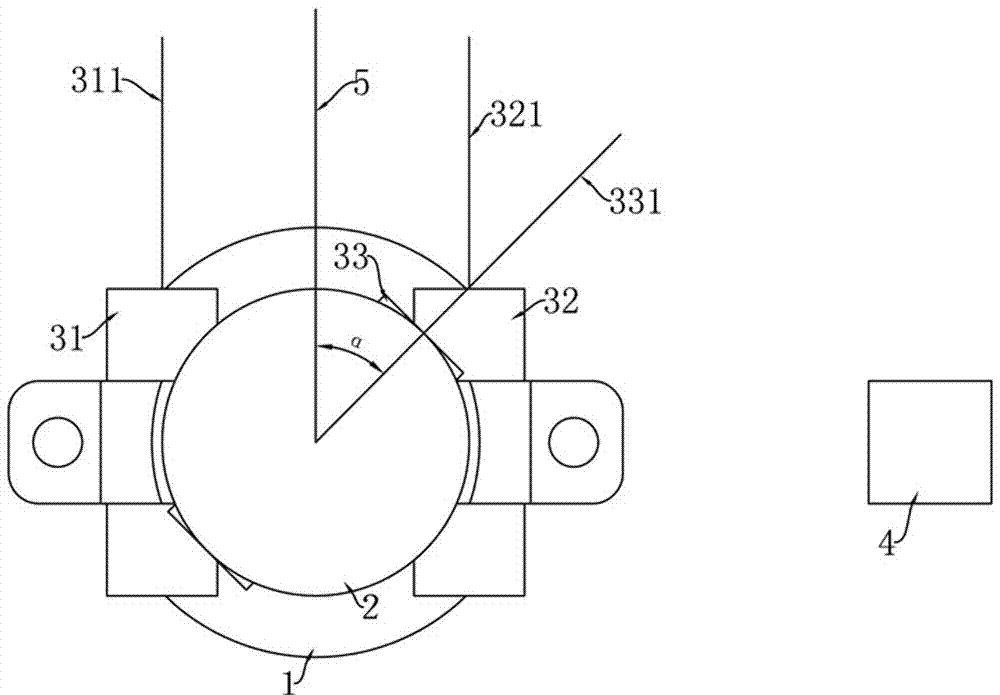
[0051] Example 1, such as Figure 1-2 As shown, the laser group 3 includes: a first laser 31, a second laser 32 and a third laser 33 which are respectively perpendicular to the preset rotation axis; the first laser 31 is used to emit a first laser plane 311, and the second laser 32 is used for In order to emit the second laser plane 321 , the third laser 33 is used to emit the third laser plane 331 .

example 2

[0052] Example 2, the laser group includes: the first laser, the second laser and the third laser respectively parallel to the preset rotation axis; it also includes: a mirror; the mirror is used to change the three lasers of the first laser, the second laser and the third laser The directions of the laser planes emitted by the laser are used to obtain the first laser plane 311 , the second laser plane 321 and the third laser plane 331 respectively.

example 3

[0053] Example 3, the laser group includes: single or multiple lasers and a beam splitter; the laser light emitted by a single or multiple lasers can be separated into the first laser plane 311, the second laser plane 321 and the third laser plane 321 conforming to the above relationship after passing through the beam splitter Laser plane 331 .

[0054] The above three implementations of the laser group 3 are not exhaustive enumeration, as long as the other can achieve "the first laser plane 311 and the second laser plane 321 are parallel to each other, and are respectively m / 2 away from the preset rotation axis and parallel to the preset rotation axis; The third laser plane 331 forms an angle β with the preset rotation axis, and β is not equal to 90°; the line located on the third laser plane 331, passing through the intersection of the third laser plane 331 and the preset rotation axis, and perpendicular to the preset rotation axis and The design scheme of the laser group 3 ...


PUM


Abstract

The invention discloses a point target space distance measurement positioning device and method, relates to the technical field of space positioning, and aims to provide the point target space distance measurement positioning device which can conduct both direction locating and distance measurement. The device comprises a driving device, a laser group, a photosensitive timing device and a synchronous device; the laser group can rotate around a preset rotating shaft at an angle speed Omega under the drive of the driving device, the laser group can emit a first laser plane, a second laser plane and a third laser plane, the first laser plane is parallel to the second laser plane, an included angle beta is formed between the third laser plane and the preset rotating shaft, and the synchronous device is located on the third laser plane, passes through an intersection point of the third laser plane and the preset rotating shaft, and is perpendicular to the straight line of the preset rotating shaft, and an included angle alpha is formed between the synchronous device and the first laser plane; the photosensitive timing device is arranged at a to-be-positioned point target, and in the rotation process of the laser group, a photosensitive timing device is capable of recording the time t1, t2 and t3 when scanned by the three laser planes respectively.

Description

technical field [0001] The invention relates to the technical field of point space positioning. Background technique [0002] The space positioning system has a very long history. From the ancient "astronography" to the modern theodolite to the modern GPS, many methods, technologies and equipment have been invented and created continuously. The positioning accuracy is getting higher and higher, and the measurement speed is getting faster and faster. It is getting faster and faster, and the cost of equipment is getting lower and lower, which fully reflects the wisdom and creativity of human beings. Among them, technologies commonly used for high-precision and rapid positioning in small indoor spaces include optical image recognition and positioning technology, ultrasonic ranging and positioning technology, radio ranging and positioning technology, laser scanning positioning technology, etc. Each of these techniques has its own advantages and limitations. For example, althou...

Claims


Application Information

Patent Timeline
IPC IPC(8): G01C3/00
CPCG01C3/00
Inventor 王磊
Owner 王磊
Why Eureka
Try Eureka