Traffic load balancing method based on leaf-spine topology structure, devices and system

A technology of topology structure and load sharing, applied in the field of mobile communication, can solve the problems of inability to guarantee load sharing and traffic load sharing, and achieve the effect of improving forwarding quality and performance, improving network bandwidth utilization, and improving user experience.

Active Publication Date: 2017-06-30
HUAWEI TECH CO LTD
View PDF2 Cites 18 Cited by
  • Summary
  • Abstract
  • Description
  • Claims
  • Application Information

AI Technical Summary

Problems solved by technology

Even if the DLB algorithm achieves the load sharing of each physical link of the local device, it cannot guarantee that the entire path under the network topology can be load shared without congestion and discarding
[0012] Therefore, no matter whether the static hash algorithm or the DLB algorithm is used, the traffic load sharing of the entire path under the leaf-spine network topology cannot be realized.

Method used


Image

  • Traffic load balancing method based on leaf-spine topology structure, devices and system
  • Traffic load balancing method based on leaf-spine topology structure, devices and system
  • Traffic load balancing method based on leaf-spine topology structure, devices and system

Examples


Embodiment Construction

[0038] The technical solutions in the embodiments of the present invention will be clearly and completely described below in conjunction with the accompanying drawings.

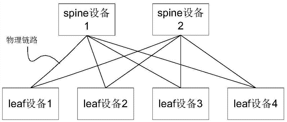
[0039] Image 6 It is a schematic diagram of the leaf-spine system architecture involved in the method for traffic load sharing based on the leaf-spine network topology provided by the embodiment of the present invention. The system includes multiple leaf devices, multiple spine devices, and multiple servers. The leaf device and the spine device are fully connected to ensure network reliability. There is no connection between the spine device and the spine device, and no connection between the leaf device and the leaf device.

[0040] Spine device 1 and spine device 2 are the backbone nodes of the bearer network and are located at the convergence layer. Leaf device 1 to leaf device 4 are leaf nodes of the bearer network and are located at the access layer.

[0041] In one example, the spine device is an Ethernet ...


PUM


Abstract

The invention relates to the field of mobile communication and particularly relates to a traffic load balancing method based on a leaf-spine topology structure, devices and a system. According to the traffic load balancing method based on the leaf-spine topology structure, a first leaf device sends a plurality of congestion detection messages to a second leaf device through a plurality of paths; each congestion detection message carries a congestion value; the congestion values are used for indicating the congestion degree of the paths passed by the congestion detection messages; and the first leaf device selects at least one path to send data to the second leaf device according to the congestion value of each path. Through application of the scheme provided by the invention, the load balancing of a whole network is realized.

Description

Technical field [0001] The present invention relates to the field of mobile communication, in particular to the traffic load sharing of an Ethernet network. Background technique [0002] In today's Ethernet network, in order to reduce the impact of link failures on services, multiple links are usually mutually backup. When the main link fails, the traffic is switched to the backup link to ensure the quality and reliability of the service Sex. However, this method cannot enable service traffic to be forwarded on the active and standby links at the same time, and cannot effectively utilize the bandwidth of the link. [0003] In order to support traffic load sharing, multiple physical links of the device are usually bundled together to form a logical link, such as figure 1 Shown. figure 1 It is a schematic diagram of a logical link formed by multiple physical links in the prior art. in figure 1 , The server is connected to device 1 through two physical links, and these two physical ...

Claims


Application Information

Patent Timeline
Patent Type & Authority Applications(China)
IPC IPC(8): H04L12/803H04L12/24H04W28/02H04W28/08
CPCH04L41/0663H04L47/125H04W28/0289H04W28/08
Inventor 姚学军王建兵
Owner HUAWEI TECH CO LTD
Why Eureka
Try Eureka