Method for dividing and implementing uplink HARQ feedback channel resources
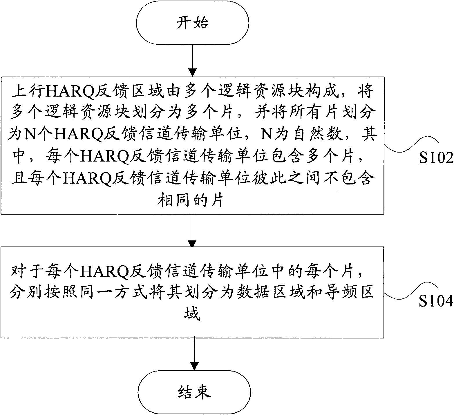
A feedback channel and feedback information technology, applied in the division and realization of uplink HARQ feedback channel, to achieve the effect of ensuring transmission performance
- Summary
- Abstract
- Description
- Claims
- Application Information
AI Technical Summary
Problems solved by technology
Method used
Image
Examples
example 1
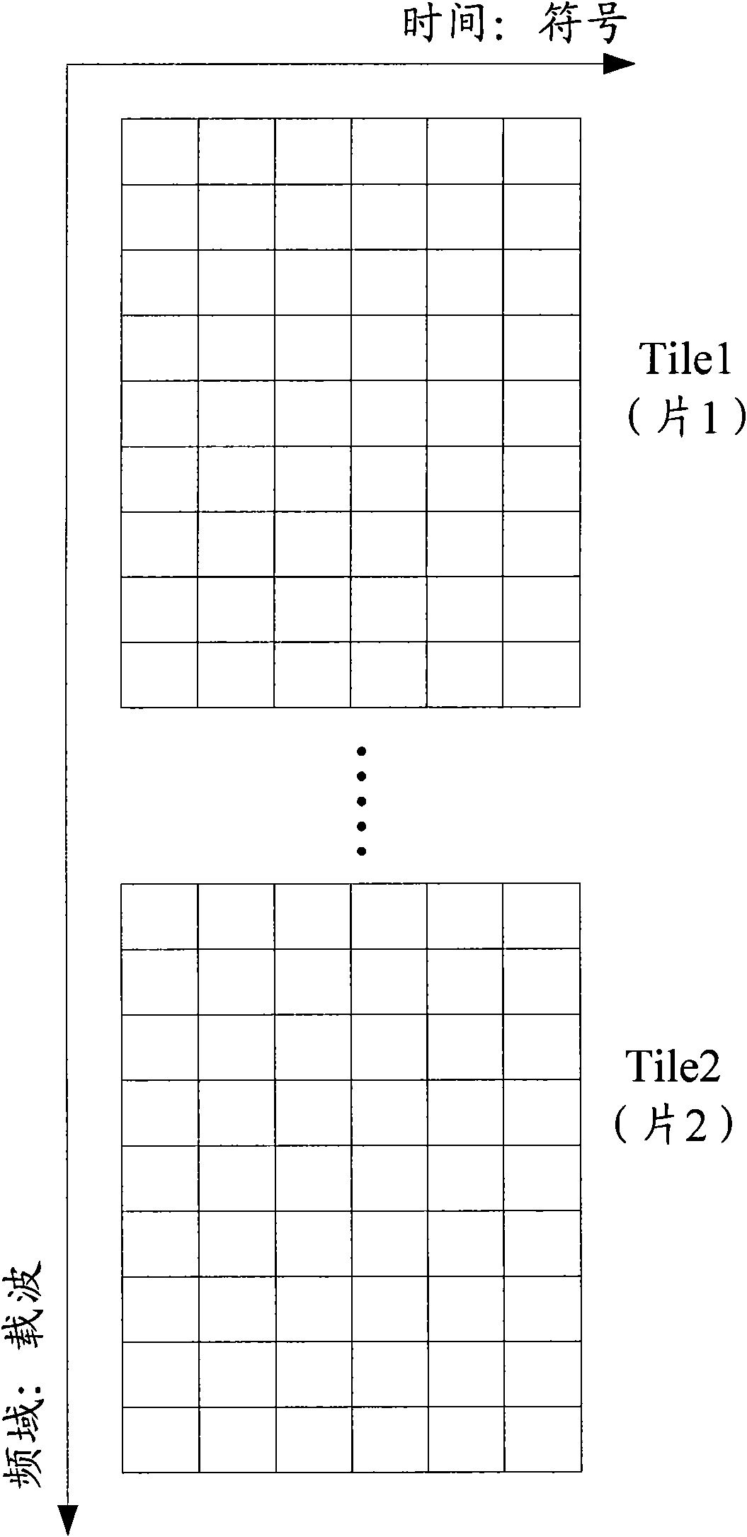
[0076] figure 2 A schematic diagram showing the structure of logical resource blocks in the uplink HARQ feedback channel region in the prior art, as shown in figure 2As shown, in an LRU (uplink logical resource block), one LRU contains 2 Tile, wherein each Tile occupies 6 consecutive symbols in the time domain and 9 subcarriers in the frequency domain, forming a 9*6 A rectangular resource block area (M=9, L=6).
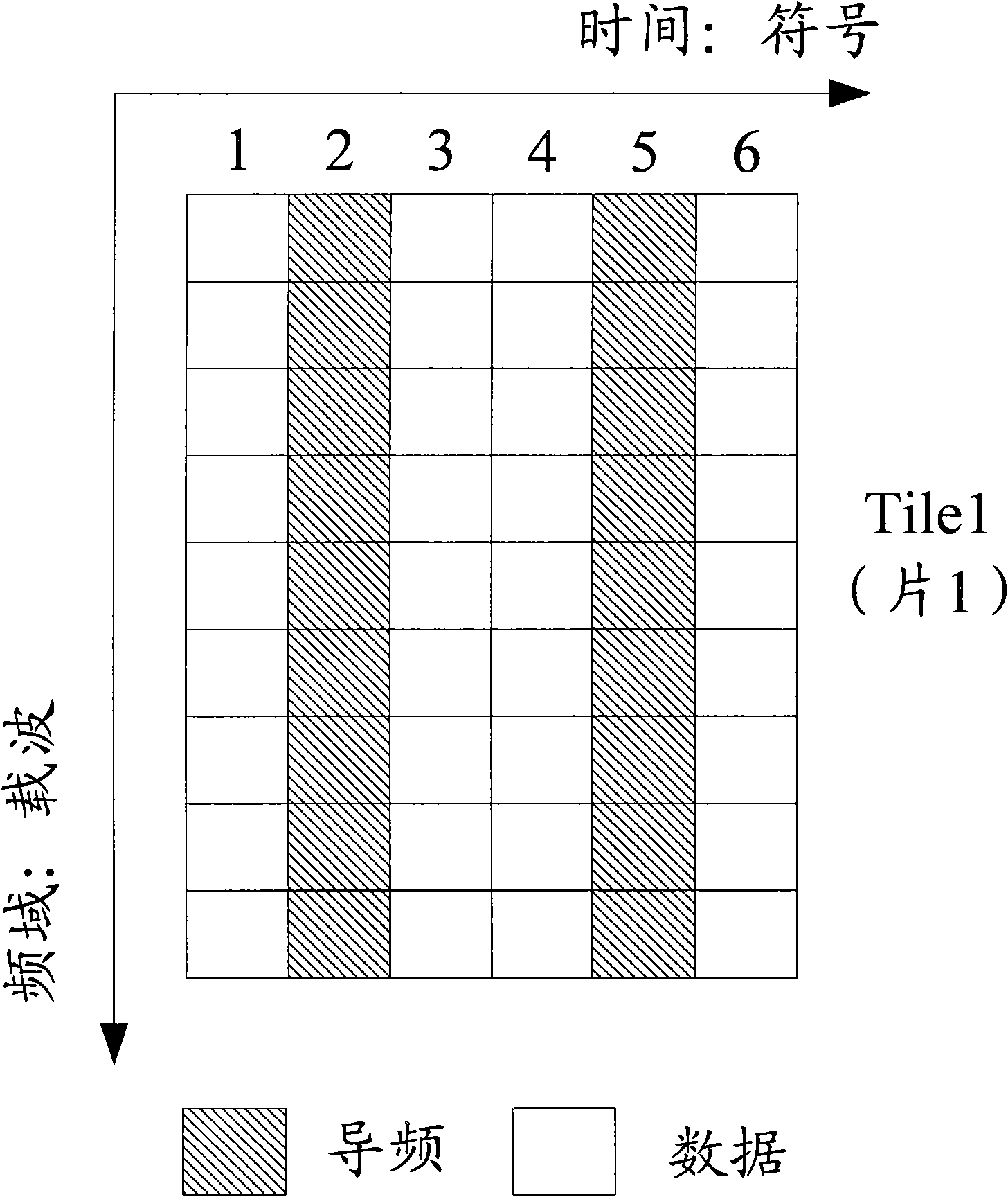
[0077] image 3 It shows a schematic diagram of the division method of the data area and the pilot area according to the first implementation, as shown in image 3 As shown, will figure 2 The two Tile shown constitute an uplink HARQ feedback channel transmission unit. Specifically, the following operations are performed on each Tile: all carriers included in symbols 1, 3, 4, and 6 are divided into data areas, where L1=4, and All subcarriers included in symbols 2 and 5 are divided into pilot regions, where L2=2.
[0078] Multiplex N=16 HARQ feedback channels in...
example 2
[0111] will be like figure 2 The two Tile in the LRU constitute an uplink HARQ feedback channel transmission unit, Figure 6 It is a schematic diagram of the division method of the data area and the pilot area according to the second implementation, such as Figure 6 As shown, the following operations are performed on each Tile: all carriers included in symbols 1, 2, 5, and 6 are divided into data regions, where L1=4, and all subcarriers included in symbols 3 and 4 are divided into pilot regions, where L2=2.
[0112] Multiplex N=8 HARQ feedback channels in the above HARQ feedback channel transmission unit, and spread the number N in the frequency domain f =4, the spreading number N in the time domain t =2, where each HARQ feedback channel occupies all subcarriers of the entire HARQ feedback channel transmission unit. Since each HARQ feedback channel repeatedly modulates the first Tile on the second Tile it contains, that is, the same operation is performed on the two Tile...
example 3
[0145] Figure 9 It shows a schematic diagram of the division method of the data area and the pilot area according to the third implementation, as shown in Figure 9 As shown, will figure 2 In one of the LRUs shown, one LRU contains 3 Tile, where each Tile occupies 6 consecutive symbols in the time domain and 6 subcarriers in the frequency domain, forming a 6*6 rectangular resource block area (M=6, L=6), these 3 Tiles constitute an uplink HARQ feedback channel transmission unit, specifically, the following operations are performed on each Tile: all carriers included in symbols 1, 3, 4, and 6 are divided into In the data region, where L1=4, all subcarriers included in symbols 2 and 5 are divided into pilot regions, where L2=2.
[0146] Multiplex N=12 HARQ feedback channels in the above-mentioned HARQ feedback channel transmission unit, and the spreading number N in the frequency domain f =6, the spreading number N in the time domain t =2, where each HARQ feedback channel o...
PUM
 Abstract
Description
Claims
Application Information
 - R&D
- Intellectual Property
- Life Sciences
- Materials
- Tech Scout
- Unparalleled Data Quality
- Higher Quality Content
- 60% Fewer Hallucinations
Browse by: Latest US Patents, China's latest patents, Technical Efficacy Thesaurus, Application Domain, Technology Topic, Popular Technical Reports.
© 2025 PatSnap. All rights reserved.Legal|Privacy policy|Modern Slavery Act Transparency Statement|Sitemap|About US| Contact US: help@patsnap.com


