Uplink transmission and configuration method, terminal, and base station

A technology of transmission method and configuration method, which is applied in the direction of transmission path separation device, transmission path sub-channel allocation, transmission system, etc., and can solve the uplink scheduling scheme without coherent transmission capability interaction information between terminal and base station, and without base station coherent transmission capability And other issues

Active Publication Date: 2019-04-09
DATANG MOBILE COMM EQUIP CO LTD
View PDF7 Cites 12 Cited by
  • Summary
  • Abstract
  • Description
  • Claims
  • Application Information

AI Technical Summary

Problems solved by technology

[0016] In the existing communication system, there is no mutual information between the terminal and the base station on the coherent transmission capability of the transmission path, and there is no uplink scheduling scheme and uplink access grant scheme for the base station based on the coherent transmission capability of the transmission path of the terminal

Method used


Image

  • Uplink transmission and configuration method, terminal, and base station
  • Uplink transmission and configuration method, terminal, and base station
  • Uplink transmission and configuration method, terminal, and base station

Examples


Embodiment Construction

[0166]Exemplary embodiments of the present disclosure will be described in more detail below with reference to the accompanying drawings. Although exemplary embodiments of the present disclosure are shown in the drawings, it should be understood that the present disclosure may be embodied in various forms and should not be limited by the embodiments set forth herein. Rather, these embodiments are provided for more thorough understanding of the present disclosure and to fully convey the scope of the present disclosure to those skilled in the art.

[0167] The uplink reference signal in the embodiments of the present invention refers to an uplink reference signal with functions such as uplink channel quality measurement, and / or beam measurement, and / or time-frequency measurement, preferably, SRS (Sounding Reference Signal, SoundingReference Signal) .

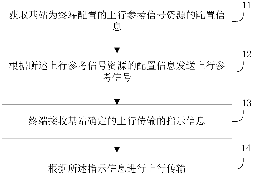
[0168] Such as figure 1 As shown, an embodiment of the present invention provides an uplink transmission method, including:

...


PUM


Abstract

The embodiment of the invention provides an uplink transmission method, an uplink configuration method, a terminal and a base station. The method at the terminal side comprises the following steps: acquiring configuration information of uplink reference signal resources configured for the terminal by the base station; sending an uplink reference signal according to the configuration information ofthe uplink reference signal resource; enabling the terminal to receive uplink transmission indication information determined by the base station; and performing uplink transmission according to the indication information. The scheme of the invention provides a sending and receiving scheme of the interaction information of the terminal and the base station with respect to the coherent transmissioncapability of the sending path, and an interaction scheme of signaling such as resource configuration, uplink access permission and the like based on the interaction scheme, thereby ensuring the uplink transmission performance of the terminal.

Description

technical field [0001] The present invention relates to the field of communication technology, in particular to an uplink transmission, a configuration method, a terminal and a base station. Background technique [0002] In LTE Rel-8, up to 4 layers of MIMO transmission can be supported. [0003] Rel-9 focuses on enhancing the MU-MIMO technology. The MU-MIMO (Multi-User MIMO) transmission of TM (Transmission Mode)-8 can support up to 4 downlink data layers. [0004] Rel-10 introduces support for 8 uplink reference signal ports to further improve the spatial resolution of channel state information, and further expands the transmission capability of SU-MIMO (Single-User MIMO) to a maximum of 8 data layers. [0005] Rel-13 and Rel-14 introduced FD-MIMO technology support to 32 ports to achieve full-dimensional and vertical beamforming. [0006] In order to further improve the MIMO technology, large-scale antenna technology is introduced into the mobile communication system. ...

Claims


Application Information

Patent Timeline
Patent Type & Authority Applications(China)
IPC IPC(8): H04L5/00H04W72/04
CPCH04L5/0048H04W72/21H04L5/0007H04L5/0023H04L5/0051H04L5/0044H04L5/0094H04B7/0639H04B7/063H04L1/0025H04B7/0456H04W72/53H04W72/51H04W8/24H04W88/06H04W88/10
Inventor 黄秋萍高秋彬塔玛拉卡·拉盖施李辉陈润华
Owner DATANG MOBILE COMM EQUIP CO LTD
Why Eureka
Try Eureka