Enclasping mechanism, and pedal device of chair

A technology of chair furniture and clamping feet, which is applied in the field of office chairs and swivel chairs. It can solve the problems of uneven holding force, insufficient holding effect, and loss of tightening function, etc., and achieves uniform holding force up and down, and is convenient for manual operation. , the effect of prolonging the service life

Pending Publication Date: 2017-07-04
UE FURNITURE CO LTD
View PDF16 Cites 1 Cited by
  • Summary
  • Abstract
  • Description
  • Claims
  • Application Information

AI Technical Summary

Problems solved by technology

[0002] Existing chairs, especially children's chairs, usually have a circular footrest, which is connected to the central sleeve through the bracket, and the central sleeve and the air rod (also called the main shaft) are tightly held and fixed. The design adopts a single-point compression fixing method, that is, the center sleeve is used to match the C-shaped sleeve, and a threaded hole is opened on the center sleeve, and the knob with the screw rod is inserted into the threaded hole and gradually tightened. When the knob is tightened, the C-shaped sleeve is squeezed to force it to be fixed on the air rod. This fixing method is not only complicated and laborious in rotating and locking, but also has the following disadvantages: The C-shaped sleeve is made of rubber material, and only the The design of the rubber material can tighten the air rod. When the knob is pressed against the C-shaped sleeve, it will cause damage to the surface of the C-shaped sleeve, and the tightening function will be lost after long-term use; moreover, it will Indirect pressure on the air rod will cause the deformation of the air rod, which will affect the lifting function of the round pedal ring; what's more, it will cause the round pedal and the bracket

Method used


Image

  • Enclasping mechanism, and pedal device of chair
  • Enclasping mechanism, and pedal device of chair
  • Enclasping mechanism, and pedal device of chair

Examples


Embodiment

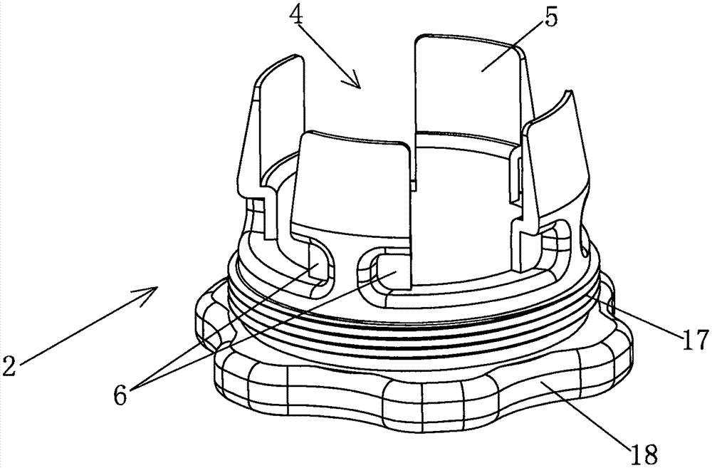
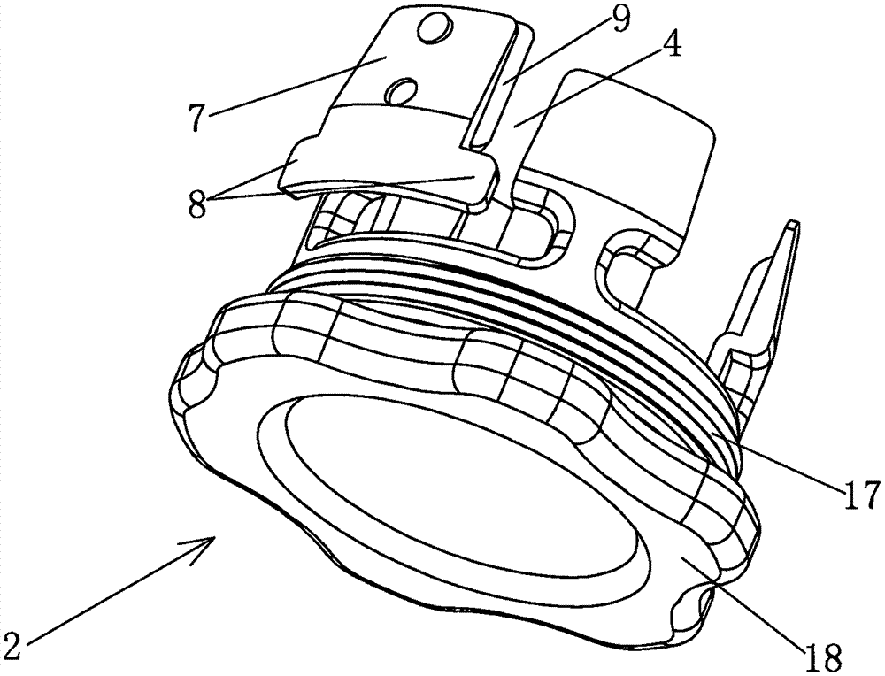
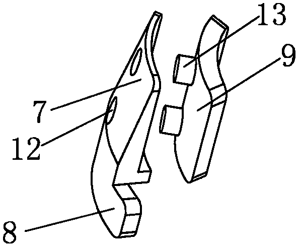
[0037] Embodiment: First define the orientation. The description of the orientation in the present invention is based on the fact that the clasping mechanism and the pedal device are installed on the chair and are in normal use. The inner sleeve is located at the lower end of the outer sleeve and the two are plugged together.

[0038] A clinging mechanism such as Figure 1~6As shown, it includes the main shaft 1, the inner sleeve 2 and the outer sleeve 3. When applied to chairs, the main shaft 1 is also called an air rod. The inner and outer are relative. In the present invention, the inner sleeve is not completely Set in the outer sleeve, only the upper end of the inner sleeve is inserted in the outer sleeve; the inner sleeve 2 and the outer sleeve 3 are made of nylon material, and the upper end of the inner sleeve 2 is provided with a plurality of axially arranged The groove 4 forms a plurality of elastically deformable fins 5 distributed in the circumferential direction, an...


PUM


Abstract

The invention discloses an enclasping mechanism, and a pedal device of a chair. The enclasping mechanism comprises a main shaft, an inner sleeve and an outer sleeve; a plurality of trench grooves are arranged in the upper end of the inner sleeve to form a plurality of circumferentially distributed fins, grooves are respectively arranged in two sides of the external surface of every fin, a briquette is arranged in every trench groove, clamping feet are respectively arranged at the left side and the right side of every briquette, the clamping feet are arranged in the grooves, a rubber sheet is inlaid in the internal surface of every briquette, and the external surface of every briquette is sloping; and the outer sleeve has oblique an inner hole cooperating with the gradient of the external surfaces of the briquettes, the upper end of the inner sleeve is inserted to the inner hole of the outer sleeve, and when the inner sleeve moves upward or the outer sleeve moves downward, the outer sleeve extrudes the briquettes to make the briquettes inward press the rubber sheets in order to make the rubber sheets closely applied to the main shaft. The briquettes are not rooted in the inner sleeve and are movable freely, and the whole briquettes and the rubber sheets are forced to move to the center in parallel when the oblique surfaces cooperate, so the up-and-down cohesion force of the briquettes and the rubber sheets is uniform.

Description

technical field [0001] The invention relates to the technical field of swivel chairs and office chairs, in particular to a clinging mechanism and a foot pedal device for chairs. Background technique [0002] Existing chairs, especially children's chairs, usually have a circular footrest, which is connected to the central sleeve through the bracket, and the central sleeve and the air rod (also called the main shaft) are tightly held and fixed. The design adopts a single-point compression fixing method, that is, the center sleeve is used to match the C-shaped sleeve, and a threaded hole is opened on the center sleeve, and the knob with the screw rod is inserted into the threaded hole and gradually tightened. When the knob is tightened, the C-shaped sleeve is squeezed to force it to be fixed on the air rod. This fixing method is not only complicated and laborious in rotating and locking, but also has the following disadvantages: The C-shaped sleeve is made of rubber material, a...

Claims


Application Information

Patent Timeline
IPC IPC(8): A47C7/50A47C7/00
CPCA47C7/00A47C7/506
Inventor 虞红潮
Owner UE FURNITURE CO LTD
Why Eureka
Try Eureka