High Frequency Surgical Cutting Ring for Flexible Endoscopy

A technology of high-frequency surgery and surgery, applied in the direction of surgery, heating surgical instruments, parts of surgical instruments, etc., can solve the problems of expensive, ring electrode manufacturing costs, etc.

Active Publication Date: 2021-08-24
君特费林 +1
View PDF10 Cites 0 Cited by
  • Summary
  • Abstract
  • Description
  • Claims
  • Application Information

AI Technical Summary

Problems solved by technology

[0008] Although it is theoretically possible to use the ring electrode to eliminate the above-mentioned problem of excessively long initial cutting delays, the manufacture of the ring electrode is very laborious and therefore expensive
[0009] Another problem when applying all the polypectomy rings that have been used so far is that neither the endoscopist nor his assistant (such as an endoscopy nurse) can observe or visibly Control: Whether the HF surgical incision loop is closed, and if so, how quickly

Method used


Image

  • High Frequency Surgical Cutting Ring for Flexible Endoscopy
  • High Frequency Surgical Cutting Ring for Flexible Endoscopy

Examples


Embodiment Construction

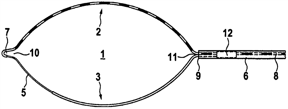
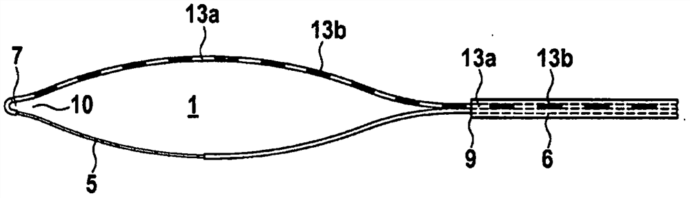
[0026] exist figure 1 A high frequency surgical cutting ring 1 for flexible endoscopy according to the present invention is shown in . The high-frequency surgical cutting ring includes a first ring part 2 and a second ring part 3 made of metal round wires and / or flat wires. These ring portions may also comprise metallic litz wires. These ring parts have a proximal end 11 and a distal end 10 respectively. The proximal ends of the ring parts together form the proximal end 11 of the ring and are connected mechanically and electrically conductively to the operating wire 8 in the catheter 6 , for example by means of a connecting element 12 . Preferably, the operating wire is much stiffer than the loop wire.

[0027] The distal ends of the ring parts 2 and 3 together form the distal end 10 of the ring 1 , which can be designed as a ring protrusion or ring tip 7 . A ring tip configured in such a way is required to be able to pull the ring completely into the distal end 9 of the c...


PUM


Abstract

The present invention relates to a polypectomy ring comprising two ring parts, with one ring part being completely electrically insulated and the other being electrically insulated only in the proximal region and not electrically insulated in the distal region. ring part.

Description

technical field [0001] The invention relates to a high-frequency surgical cutting ring for an instrument or as part of an instrument for the endoscopically controlled removal of polypoid or flattened growths of diseased mucosal regions (so-called lesions) of the gastrointestinal tract. Additionally, these instruments are known as polypectomy devices or (by part for whole) polypectomy rings. [0002] technical background [0003] One of the first such devices was described in German Utility Model Patent No. 71115781 in 1971. Today, as then, these instruments basically consist of a flexible catheter about 2 m long made of plastic, a metallic steering wire movable in the catheter, a high-frequency surgical Surgical cutting ring and operating handle at the other end (the so-called proximal end) of the manipulation wire and catheter. For more than forty years, catheters and cutting rings of these instruments have been used through the so-called instrument channel or working chan...

Claims


Application Information

Patent Timeline
Patent Type & Authority Patents(China)
IPC IPC(8): A61B18/14
CPCA61B18/14A61B2018/00494A61B2018/00601A61B2018/00107A61B2018/1407
Inventor 君特·费林M·黑尔尼克
Owner 君特费林
Why Eureka
Try Eureka