An ultrasonic scanning guidance device and an ultrasonic scanning guidance method

An ultrasonic scanning and guiding device technology, applied in the field of ultrasonic scanning, can solve the problems of inconvenience of use, ultrasonic probe guidance, high requirements for professional operators, etc., to achieve convenient operation, reduce professional dependence, and achieve the effect of separation

Active Publication Date: 2020-11-27
QISDA SUZHOU +1
View PDF9 Cites 0 Cited by
  • Summary
  • Abstract
  • Description
  • Claims
  • Application Information

AI Technical Summary

Problems solved by technology

[0002] Ultrasound has become a commonly used tool for disease diagnosis. However, the interpretation of ultrasound still requires professional physicians or sonographers; for remote areas where medical resources are scarce, professional personnel are still required to operate and judge when using ultrasound diagnosis and treatment tools. Obviously, in medical diagnosis The requirements for professional operators are too high, and it is very inconvenient to use
[0003] In the prior art, it is conceivable to detect and transmit the ultrasonic detection image to the doctor for observation through three-dimensional space, or guide the follow-up doctor to adjust the angle during the ultrasonic detection through the previously detected spatial deflection angle to find the accurate scanning position, and then It only involves how to calibrate the ultrasound probe at a specific position, and how to guide the ultrasound probe to the desired detection position is still an insurmountable problem in the existing technology, which leads to the indispensability of professional physicians or sonographers during on-site diagnosis.

Method used


Image

  • An ultrasonic scanning guidance device and an ultrasonic scanning guidance method
  • An ultrasonic scanning guidance device and an ultrasonic scanning guidance method
  • An ultrasonic scanning guidance device and an ultrasonic scanning guidance method

Examples


Embodiment Construction

[0023] In order to have a further understanding of the purpose, structure, features, and functions of the present invention, the following detailed descriptions are provided in conjunction with the embodiments.

[0024] Certain terms are used in the description and claims to refer to particular elements. Those of ordinary skill in the art will appreciate that manufacturers may refer to the same element by different terms. The specification and claims do not use the difference in name as a way to distinguish components, but use the difference in function of components as a criterion for distinguishing. "Include" mentioned throughout the specification and claims is an open term, so it should be interpreted as "including but not limited to".

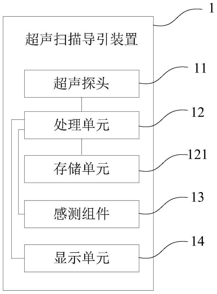
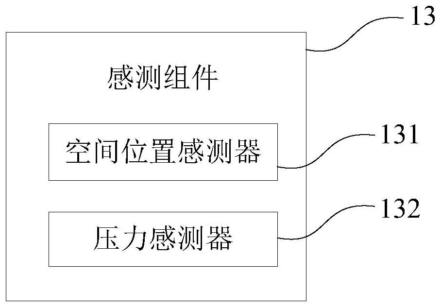
[0025] refer to Figure 1 to Figure 2 As shown, it discloses a schematic structural view of the first embodiment of the ultrasonic scanning guide device 1 of the present invention, figure 1 It is a structural block diagram of the ultraso...


PUM


Abstract

The invention discloses an ultrasonic scanning guidance device and method. The device comprises an image database, an ultrasonic probe, a sensing component and a processing unit, wherein the image database comprises multiple characteristic images and multiple characteristic position messages, and the multiple characteristic images correspond to the multiple characteristic position messages in a one-to-one mode; and the ultrasonic probe is used for scanning an object to acquire a real-time regional image, the sensing component is used for acquiring a real-time characteristic position message of the ultrasonic probe relative to the object, and the processing unit is used for acquiring a first path according to the real-time regional image, the real-time characteristic position message, the multiple characteristic images, the multiple characteristic position messages and a target message, so as to guide the ultrasonic probe to move to a target position along the first path, and the target message corresponds to the target position. In this way, the ultrasonic probe is guided to the specific target position, accurate and professional scanning is realized, users do not need to decide how to move the ultrasonic probe by themselves, operation is convenient, and dependence on the professionality of users is reduced.

Description

technical field [0001] The invention relates to the field of ultrasonic scanning, in particular to a device and method for guiding the movement of an ultrasonic probe during human body scanning. Background technique [0002] Ultrasound has become a commonly used tool for disease diagnosis. However, the interpretation of ultrasound still requires professional physicians or sonographers; for remote areas where medical resources are scarce, professional personnel are still required to operate and judge when using ultrasound diagnosis and treatment tools. Obviously, in medical diagnosis Sometimes the requirements for professional operators are too high, and it is very inconvenient to use. [0003] In the prior art, it is conceivable to detect and transmit the ultrasonic detection image to the doctor for observation through three-dimensional space, or guide the follow-up doctor to adjust the angle during the ultrasonic detection through the previously detected spatial deflection ...

Claims


Application Information

Patent Timeline
Patent Type & Authority Patents(China)
IPC IPC(8): A61B8/00
CPCA61B8/00A61B8/44A61B8/4444A61B8/46
Inventor 董昱腾
Owner QISDA SUZHOU
Why Eureka
Try Eureka