Electric welding device

A technology of power supply device and sliding groove, which is applied in arc welding equipment, welding equipment, manufacturing tools, etc., can solve the problems of unsatisfactory and self-locking structure without guarantee, and achieve convenient operation, improve work efficiency, safety and structure. simple effect

Active Publication Date: 2017-07-07
南通卓效自动化有限公司
View PDF7 Cites 0 Cited by
  • Summary
  • Abstract
  • Description
  • Claims
  • Application Information

AI Technical Summary

Problems solved by technology

[0002] At present, electric welding machines are used more and more widely, and they can work normally only by locking and connecting electricity. Therefore, whether the electric welding machine is firmly locked is the basis for determining whether

Method used


Image

  • Electric welding device
  • Electric welding device
  • Electric welding device

Examples


Embodiment Construction

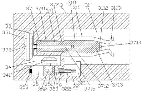
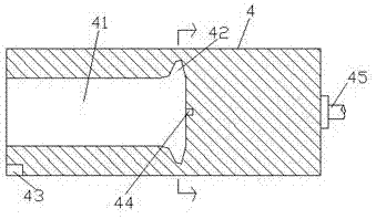
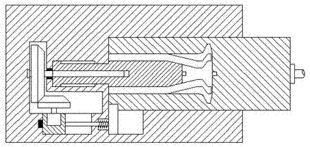
[0025] Such as Figure 1-Figure 6 As shown, an electric welding device of the present invention includes a power supply 2 and a gun holder 4, and is characterized in that a cavity 31 is provided in the right end surface of the power supply 2, and a cavity 31 is provided in the right end surface of the power supply 2. The longitudinal groove 22 extending downwards, the cavity 31 is provided with a power supply device 3, the right end surface of the power supply device 3 is provided with a locking groove 31, and the power supply device on the left side of the locking groove 31 3 is provided with a first sliding groove 37, the power supply device 3 on the left side of the first sliding groove 37 is provided with a first cavity 33, and the power supply device below the first sliding groove 37 3 is provided with a second cavity 34 whose left end intersects with the bottom of the first cavity 33, and a metal spring bar 311 is fixed on the left inner wall of the locking groove 31 cor...


PUM


Abstract

The invention discloses an electric welding device comprising a power supply department and a gun seat; the right end surface of the power supply department is internally provided with a cavity and a longitudinal groove which downwards extends; the cavity is internally provided with a power supply device; a locking groove is formed in the right end surface of the power supply device; a first sliding groove is formed in the power supply device at the left side of the locking groove; a first cavity is arranged in the power supply device at the left side of the first sliding groove; the power supply device located below the first sliding groove is internally provided with a second cavity of which the left side end passes through the bottom of the first cavity; metal spring rods are fixedly arranged on the inner wall of the left side of the locking groove in a vertically corresponding way; the first sliding groove is internally provided with a power supply pushing part; and an extension part at the right side of the power supply pushing part extends into the locking groove. The electric welding device is simple in structure and convenient to operate; and when the gun seat is inserted, driving and locking connection is automatically controlled, and meanwhile, automatic power supply connection is completed, so that the work efficiency is increased and the safety is improved.

Description

technical field [0001] The invention relates to the technical field of welding, in particular to an electric welding device. Background technique [0002] At present, electric welding machines are used more and more widely, and they can work normally only by locking and connecting electricity. Therefore, whether the electric welding machine is firmly locked is the basis for determining whether the electric welding machine can work normally. However, the existing electric welding machine locking structure There is no self-locking structure to ensure that it will not loosen, which has great disadvantages and cannot meet the existing needs. Contents of the invention [0003] The technical problem to be solved by the present invention is to provide an electric welding device, which can solve the above-mentioned problems in the prior art. [0004] The present invention is achieved through the following technical solutions: An electric welding device of the present invention in...

Claims


Application Information

Patent Timeline
IPC IPC(8): B23K9/10B23K9/00
CPCB23K9/00B23K9/1006
Inventor 蔡玉君
Owner 南通卓效自动化有限公司
Why Eureka
Try Eureka