
Trolley with locking mechanism

A trolley and pin stop technology, applied in the field of transport trolleys, can solve the problems of brake pedal interference and inability to erect, and achieve the effects of reducing assembly volume, realizing cost, and ensuring safety.

Active Publication Date: 2019-04-05
ネオスター
View PDF7 Cites 0 Cited by
  • Summary
  • Abstract
  • Description
  • Claims
  • Application Information

AI Technical Summary

Problems solved by technology

In addition, when the trolley is stored in an upright state, there is a problem that the brake pedal interferes and cannot be erected.

Method used


Image

  • Trolley with locking mechanism
  • Trolley with locking mechanism
  • Trolley with locking mechanism

Examples


Embodiment Construction

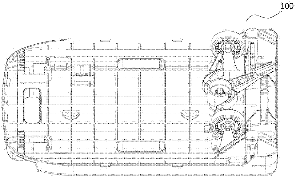
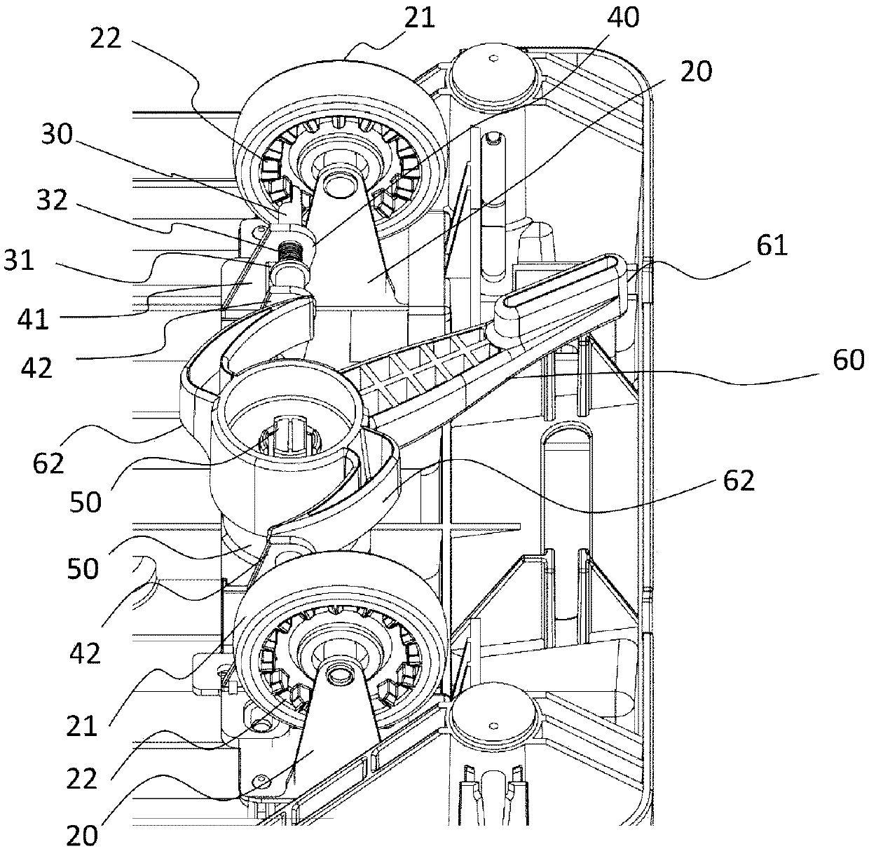
[0047] figure 1 A perspective view showing a trolley in one embodiment of the present invention. figure 2 An enlarged perspective view showing a trolley in one embodiment of the present invention.

[0048] First, the structure of the trolley 100 in one embodiment of the present invention will be described.

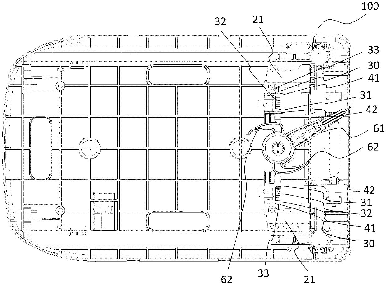
[0049] The trolley 100 has a stage 10 (the stage 10 such as Figure 6 As shown), caster frames 20 are respectively provided on the left and right sides of the rear side of the bottom surface (back surface) of the stage 10, and wheels 21 are respectively provided on the caster frames 20. On both sides of the wheel 21 or at least on the inner side, a plurality of horizontal recesses 22 are formed over the entire ring. The wheel 21 can be locked by moving the wheel lock pin 30 in and out of the concave portion 22 in the width direction of the dolly 100 .

[0050] The stage 10 is not limited, and may be made of synthetic resin, metal, or wood, and is formed in a substanti...


PUM


Abstract

The present invention provides a trolley without the problem that the locking lever portion protrudes rearward from the bottom surface of the trolley, can prevent the locking lever portion from contacting obstacles in advance, and can ensure safety between the operator and the operator when the trolley is transported and stopped. The trolley is safe and can maintain an upright state during storage, enabling space-saving storage or storage. When locking, the locking lever portion of the rotating body is rotated, and the cam portion of the rotating body resists the elastic force of the pressing spring to increase the advancing range of the wheel locking pin in the width direction, so that the wheel locking pin moves in the width direction of the trolley. Move up, so that the end of the wheel lock pin engages with the concave part of the wheel. When unlocking, the lock lever is rotated in the opposite direction to that of locking the rotating body. The cam portion of the rotating body reduces the force of the wheel locking pin. The push width in the width direction is solved by pressing the flange portion of the wheel lock pin and the wheel-side axle support portion by the elastic force of the pressing spring so that the end portion of the wheel lock pin does not mesh with the concave portion of the wheel.

Description

technical field [0001] The present invention relates to a trolley used for conveying articles, and more particularly to a trolley having a small mounting surface and a lock mechanism. Background technique [0002] Currently, Patent Document 1 or Patent Document 2 has been proposed as a locking mechanism for a trolley capable of placing and conveying articles. [0003] Patent Document 1 is a groundable locking mechanism arranged on a trolley with wheels. The locking mechanism includes a support body connected to the lower part of the trolley and can be grounded and a locking device arranged on the support body. The support body includes; A base member connected to the lower part of the trolley and formed as a first cylinder member that is quadrangular in plan view and at least opened at the bottom; a foot member that has a second cylinder member capable of contacting the ground and formed in a quadrangle in plan view; And the 3rd cylindrical member that is positioned at the ...

Claims


Application Information

Patent Timeline
Patent Type & Authority Patents(China)
IPC IPC(8): B62B5/04B60T1/00
CPCB60T1/005B62B5/04B60B33/0086B60B33/0092B62B5/0476
Inventor 星川和胤
Owner ネオスター
Learn More