Method and device for fixing a plastic component to a carrying component

A technology for plastic components, fixtures, applied in the direction of connecting components, transportation and packaging, superstructure, etc.

Active Publication Date: 2017-07-07
MAN NUTZFAHRZEUGE AG
View PDF6 Cites 0 Cited by
  • Summary
  • Abstract
  • Description
  • Claims
  • Application Information

AI Technical Summary

Problems solved by technology

The consequence of such twisting is a negative impact on the cushioning performance of the rubber-metal buffer 4 and a limitation on the service life of the rubber-metal buffer 4

Method used


Image

  • Method and device for fixing a plastic component to a carrying component
  • Method and device for fixing a plastic component to a carrying component
  • Method and device for fixing a plastic component to a carrying component

Examples


Embodiment Construction

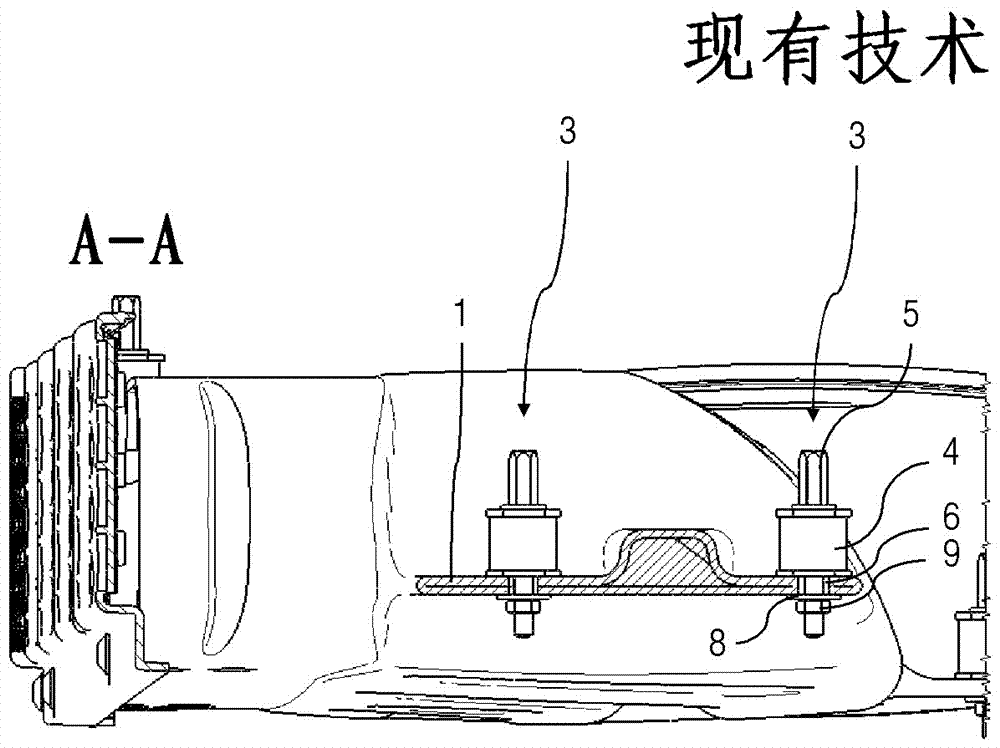
[0029] image 3 A perspective exploded view of a fastening device 15 according to an exemplary embodiment of the invention is shown. The fastening device 15 serves to fasten the plastic component 1 , here the plastic air intake shaft 1 , on the supporting component 2 . In the example shown, the supporting component is the rear cab wall of a commercial vehicle. To this end, the air intake shaft 1 has a tapered section 1 a at its upper end, which has two through-holes 7 . A metal bushing 6 is pressed into each through hole 7 .

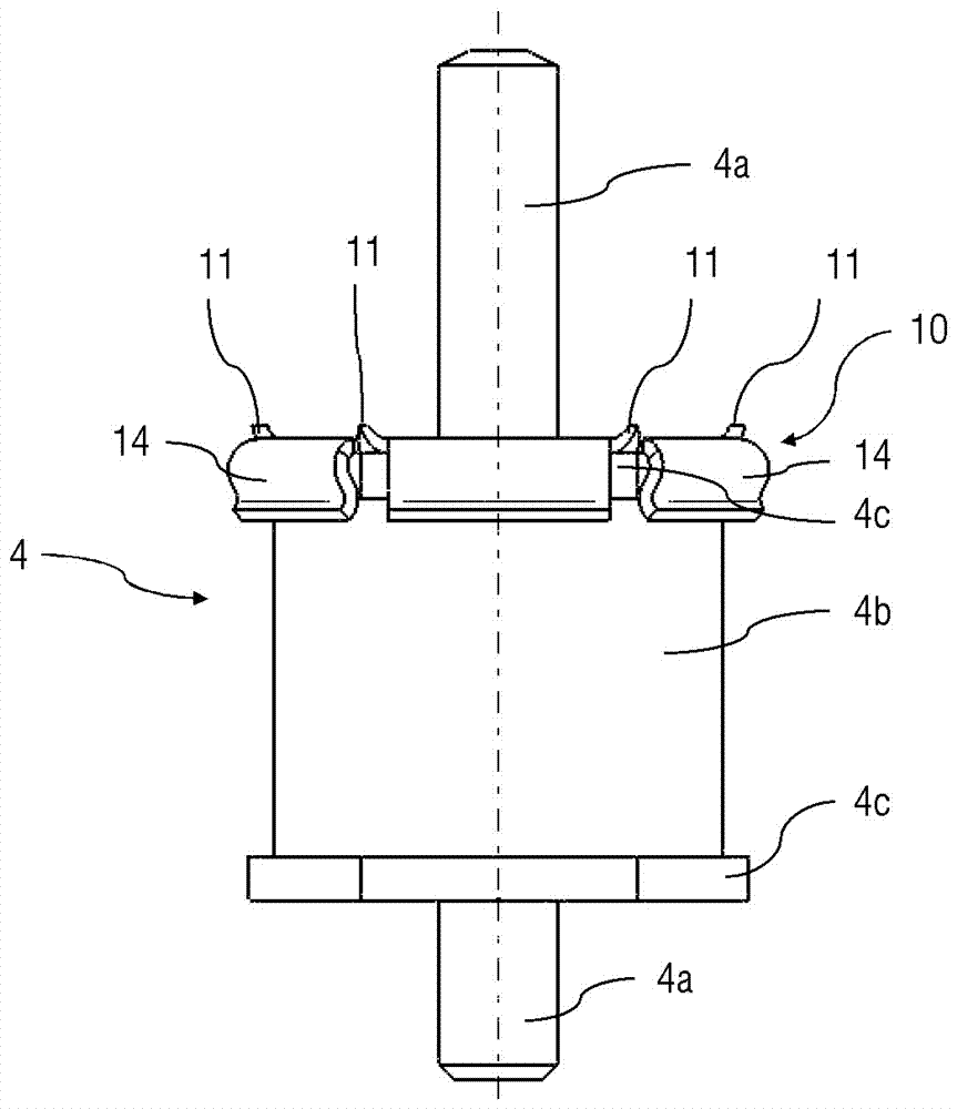
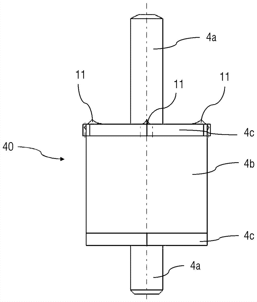
[0030] In order to decouple the air intake shaft 1 from the driver's cab in terms of vibration, the air inlet shaft 1 is fastened together with the rubber-metal damper 4 to the rear wall 2 of the driver's cab. The rubber-metal buffers 4 used here are respectively composed of two metal discs 4c and a cylindrical rubber part or rubber body 4b arranged between the two metal discs 4c. The two metal disks 4c are fixedly connected with the rubber piece 4b ...


PUM


Abstract

The present disclosure relates to a method and device for fastening a plastics component to a load-bearing component. The fastening device includes a plastics component (1) which is fastened to the load-bearing component (2) by a screw connection, and a rubber-metal buffer (4) which is arranged as a resilient support between the load-bearing component (2) and the plastics component (1). The fastening device further comprises at least one metal tip (11) which is arranged between the rubber-metal buffer (4) and the plastics component (1), and which protrudes from a metal disk (10) in the direction of the plastics component (1) and engages at least partially in a surface of the plastics component (1) when the plastics component (1) is screwed to the load-bearing component (2).

Description

technical field [0001] The invention relates to a fastening device according to the preamble of claim 1 for fastening a plastic component to a supporting component. Furthermore, the invention relates to a method according to the preamble of claim 10 for fastening a plastic component to a supporting component. Background technique [0002] It is known from practice to fasten the untreated air channel (Rohluftkanal) of the truck to the rear wall of the cab. The untreated channel is subsequently also referred to as an air intake shaft or an untreated air shaft. In order to decouple the air intake shaft from the driver's cab in terms of vibration, the air intake shaft is fastened to the rear wall of the driver's cab with rubber-metal buffers. [0003] This is exemplary in figure 1 shown in figure 1 A view is shown looking in the direction of travel towards the rear wall 2 of the driver's cab of the truck. The air intake shaft is denoted by reference number 1 and is fastened...

Claims


Application Information

Patent Timeline
Patent Type & Authority Applications(China)
IPC IPC(8): F16B13/10F16B43/00
CPCB60H1/34F16B31/00F16B39/24B60H1/244B60H2001/00242B60H1/00007B62D33/0617B62D33/06F16B13/04F16B43/00F16B13/10F16B5/0241F16F1/3732B60H1/00521B60H1/00564F16F15/085
Inventor R.普赖斯T.海因德尔
Owner MAN NUTZFAHRZEUGE AG
Why Eureka
Try Eureka