Gauge supporting device
A technology of supporting devices and checking tools, which is applied in the direction of supporting machines, engine frames, mechanical equipment, etc., can solve the problems of low work efficiency, heavy workload, complicated operation of support components, etc., and achieve the goal of facilitating operation and improving work efficiency Effect
- Summary
- Abstract
- Description
- Claims
- Application Information
AI Technical Summary
Problems solved by technology
Method used
Image

Examples
Embodiment Construction
[0037] The technical solution of the present invention is described in detail below through the examples, and the following examples are only exemplary and can only be used to explain and illustrate the technical solution of the present invention, rather than being interpreted as a limitation to the technical solution of the present invention.
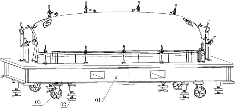
[0038] The application provides a checking device supporting device, such as Figure 3 to Figure 8 As shown, it includes a mounting plate 1, a driving pedal 9, a first rotating shaft 5, a second rotating shaft 6, a third rotating shaft 7, a return pedal 8, a base plate 3, square steel 2 and a movable rod 4.
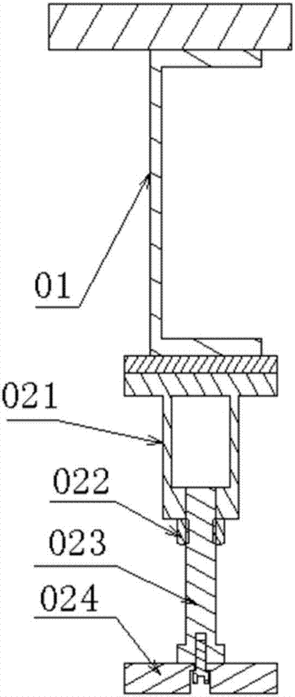
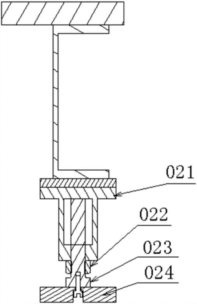
[0039] The lower surface of the mounting plate 1 is fixedly connected with the lower end of the square steel 2; the lower end of the movable rod 4 is fixedly connected with the upper surface of the bottom plate 3.
[0040] The mounting plate 1 is a rectangular steel plate, and the mounting hole 101 is provided on the mounting plat...
PUM
 Abstract
Description
Claims
Application Information
 - Generate Ideas
- Intellectual Property
- Life Sciences
- Materials
- Tech Scout
- Unparalleled Data Quality
- Higher Quality Content
- 60% Fewer Hallucinations
Browse by: Latest US Patents, China's latest patents, Technical Efficacy Thesaurus, Application Domain, Technology Topic, Popular Technical Reports.
© 2025 PatSnap. All rights reserved.Legal|Privacy policy|Modern Slavery Act Transparency Statement|Sitemap|About US| Contact US: help@patsnap.com