
Pathological tissue dehydration device and pathological tissue dehydration method

A dehydration device and tissue technology, which is applied in the field of medical or experimental equipment, can solve problems such as decline and tissue failure to reach the predetermined concentration of replacement, and achieve the effect of ensuring dehydration quality and sufficient replacement

Inactive Publication Date: 2017-07-07
曾丹平
View PDF3 Cites 3 Cited by
  • Summary
  • Abstract
  • Description
  • Claims
  • Application Information

AI Technical Summary

Problems solved by technology

[0005] The purpose of the present invention is to provide a pathological tissue dehydration device and a pathological tissue dehydration method to solve the technical problem in the prior art that the reagent concentration will continue to decrease during soaking, resulting in the tissue failing to reach the predetermined concentration that needs to be replaced

Method used


Image

  • Pathological tissue dehydration device and pathological tissue dehydration method

Examples


Embodiment approach

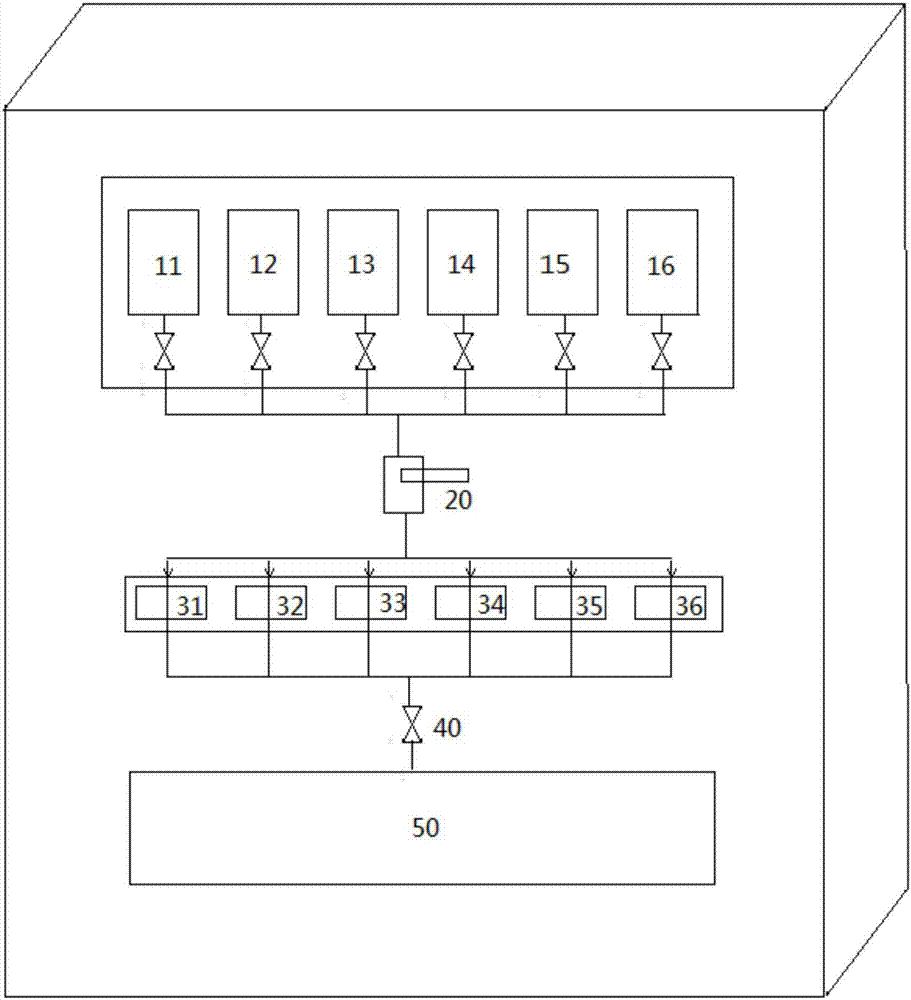
[0022] According to a typical embodiment of the present invention, a pathological tissue dehydration device is provided. The pathological tissue dehydration device includes: a plurality of reagent barrels for holding different reagents, the bottom of the reagent barrels is provided with a reagent outlet; a dropper with a reagent inlet and a reagent outlet, and a plurality of pathological tissue to be dehydrated The pathological tissue tray of the tissue; the reagent inlet end of the dropper is connected with the reagent outlet of the reagent barrel, and the reagent outlet end of the dropper is located above the pathological tissue tray, which is used to continuously and evenly add the reagent into the pathological tissue tray.

[0023] In the pathological tissue dehydration device of the present invention, the reagent outlet end of the dropper is located above the pathological tissue tray, and is used to continuously and evenly add the reagent into the pathological tissue tray,...

Embodiment 1

[0034] Such as figure 1 As shown, the pathological tissue dehydration device includes: a plurality of reagent barrels of different reagents (for example, 11, 12, 13, 14, 15, 16 shown in the figure, the number of case tissue trays can be set according to actual needs), the bottom of the reagent barrel A reagent outlet is provided; a dropper with a reagent inlet port and a reagent outlet port, and a plurality of pathological tissue trays (such as illustrations 31, 32, 33, 34, 35, 36 for holding the pathological tissues to be dehydrated can be obtained according to It is actually necessary to set the number of case tissue trays); the reagent inlet end of the dropper is connected with the reagent outlet of the reagent bucket, and the reagent outlet end of the dropper is located above the pathological tissue tray, which is used to drip the reagent into the pathological tissue tray. Of course, depending on the number of tissue samples, a single dropper or multiple side-by-side dropp...


PUM


Abstract

The invention discloses a pathological tissue dehydration device and a pathological tissue dehydration method. The pathological tissue dehydration device comprises a plurality of reagent barrels, a dropper and a pathological tissue tray, wherein the reagent barrels are used for accommodating different reagents, and reagent outlets are arranged at the bottoms of the reagent barrels; the dropper is provided with a reagent inlet end and a reagent outlet end, and the reagent inlet end of the dropper is communicated with the reagent outlet of the reagent barrel; and the pathological tissue tray is used for accommodating to-be-dehydrated pathological tissue and reagents, and is provided with a reagent outlet allowing the reagents to flow out; and the reagent outlet end of the dropper is positioned above the pathological tissue tray, and is used for continuously and uniformly adding the reagents to the pathological tissue tray. The dropper is used for continuously and uniformly adding the reagents to the pathological tissue tray, meanwhile, the reagents in the pathological tissue tray continuously flow out, so as to dehydrate the pathological tissue in the flowing reagents. Thus, the concentrations of the reagents nearly remain unchanged in soaking, so as to ensure sufficient replacement and ensure dehydration quality.

Description

technical field [0001] The invention relates to the technical field of medical or experimental equipment and methods, in particular to a pathological tissue dehydration device and a pathological tissue dehydration method. Background technique [0002] The dehydration of pathological tissue cell specimens adopts the principle of physical replacement, replacing the water in the tissue cells with paraffin. [0003] Since water and paraffin are immiscible, an intermediate conversion is required. The reagents needed are formalin, alcohol, xylene, paraffin. That is to say, the water in the tissue is completely replaced by alcohol after soaking in formalin, then xylene, and finally paraffin. The adequacy of replacement plays a very important role in the quality of the later effect. Poor dehydration will have a huge negative impact on the later steps, and in serious cases will directly lead to the inability to complete the work. [0004] In the actual application process, the tr...

Claims


Application Information

Patent Timeline
IPC IPC(8): G01N1/28
CPCG01N1/28
Inventor 曾丹平
Owner 曾丹平
Learn More