Overall performance testing rack of numerical control ultrasonic cutting sound main shaft

A comprehensive performance testing and ultrasonic cutting technology, applied in the testing of mechanical components, testing of machine/structural components, measuring devices, etc. Ultrasonic spindle with load comprehensive test and other issues, to facilitate comprehensive and follow-up analysis, improve performance test effect and efficiency, and shorten the research and development cycle

Inactive Publication Date: 2015-07-15
HANGZHOU DIANZI UNIV
View PDF7 Cites 0 Cited by
  • Summary
  • Abstract
  • Description
  • Claims
  • Application Information

AI Technical Summary

Problems solved by technology

In addition, at present, ultrasonic cutting acoustic spindles often only perform single-point scattered tests of single performance, lack of comprehensive and systematic analysis of ultrasonic cutting acoustic spindles, and lack of comprehensive testing of ultrasonic cutting spindles with load. It is difficult to fully integrate and utilize these test data. The efficiency and effect of performance testing are not ideal, which seriously affects the research and development of high-performance ultrasonic cutting sound spindle

Method used


Image

  • Overall performance testing rack of numerical control ultrasonic cutting sound main shaft
  • Overall performance testing rack of numerical control ultrasonic cutting sound main shaft
  • Overall performance testing rack of numerical control ultrasonic cutting sound main shaft

Examples


Embodiment 1

[0045] The following is an example of point-by-point CNC testing of the ultrasonic spindle section profile with a high-precision non-contact laser displacement probe to describe the action process:

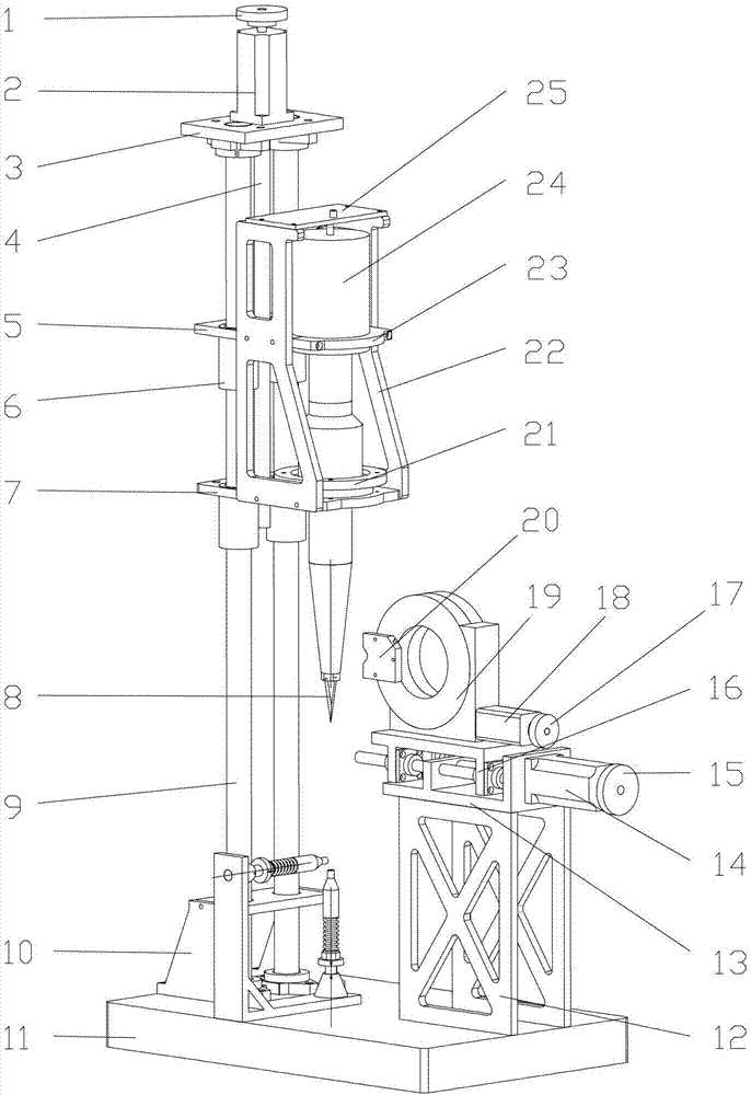
[0046] First, the clamping of the ultrasonic cutting sound main shaft 24 and the test probe 20, the sound main shaft lower pressure plate 21 is enclosed within its flange ring from the upper end of the ultrasonic cutting sound main shaft 24, so that the stepped hole on the sound main shaft lower pressure plate 21 is aligned with the main shaft. The flange ring cooperates, then the main shaft is put into the stepped hole of the lower fixed plate 7 and the stepped hole is matched with the flange ring. Connect and pre-tighten the lower pressure plate 21 of the acoustic main shaft with the lower fixing plate 7 of the acoustic main shaft with bolts. Then the pressure plate 23 on the sound main shaft is fastened on the fixed plate 5 on the sound main shaft with bolts, and then the bolts...

Embodiment 2

[0050] The following takes the measurement of the impedance characteristics of the ultrasonic cutting spindle under different loads as an example to describe the action process:

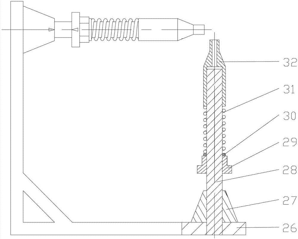
[0051]Since the gantry can complete all measurements in one clamping, the measurement process is mainly described. The installation process of the ultrasonic cutting sound spindle 24 is the same as that in Embodiment 1, so it is assumed here that the ultrasonic cutting sound spindle 24 has been installed. . First, the vertical ball screw 4 is driven to rotate by controlling the vertical servo motor 2 or the vertical motor handwheel 1, and then the ball screw pair drives the fixture and the test cutting sound main shaft 24 to move downward along the vertical linear guide rail 9 to make the ultrasonic cutting tool 8 The tip and the two axial and radial force rods 32 of the simulated load system are just in contact with each other, and then the positive and negative electrodes of the main shaft drawn ou...


PUM


Abstract

The invention discloses an overall performance testing rack of a numerical control ultrasonic cutting sound main shaft. The overall performance testing rack comprises a base. Perpendicular linear guide rails, an artificial load device and a radial movement base are installed on the base. The perpendicular linear guide rails are in sliding fit with the ultrasonic cutting sound main shaft. The artificial load device is provided with two force application rods. The two force application rods are located at the axial position and the radial position of a cutting tool nose of the ultrasonic cutting sound main shaft respectively and used for applying artificial loads to the cutting tool nose. The radial movement base is provided with a testing probe which can move towards the ultrasonic cutting sound main shaft in a radial mode and rotate. According to the overall performance testing rack of the numerical control ultrasonic cutting sound main shaft, the testing site and various costs can be reduced, the measurement on different parameters under the same installation condition is provided, the testing errors under different installation conditions are reduced, the testing effect and the testing efficiency on the performance of the ultrasonic cutting sound main shaft are improved, and test bases are provided for the further perfection and the further improvement of the performance of the ultrasonic cutting sound main shaft.

Description

technical field [0001] The invention relates to a bench for comprehensive performance testing of a numerically controlled ultrasonic cutting acoustic spindle, more precisely, a bench capable of providing testing of main performance parameters for an ultrasonic cutting acoustic spindle through the coordinated action of a numerical control and a cylindrical polar coordinate transmission mechanism . Background technique [0002] The ultrasonic cutting sound spindle is the main body and key to realize the ultrasonic cutting of emerging composite materials. It mainly consists of ultrasonic transducers, horns and cutting tools. The transducer generates longitudinal vibration, and then transmits the vibration to the cutter through the amplification effect of the horn, providing stable and reliable sound energy for the longitudinal vibration of the cutting tip. Its research involves multiple disciplines such as vibration mechanics, vibration cutting, control science and engineering...

Claims


Application Information

Patent Timeline
Patent Type & Authority Patents(China)
IPC IPC(8): G01M13/00
Inventor 陆志平韩丽轩于保华胡小平赵双双
Owner HANGZHOU DIANZI UNIV
Why Eureka
Try Eureka