A scanning tunneling microscope structure using motor-scanning head separation technology

A separation technology and scanning tunneling technology, applied in the field of scanning tunneling microscope structure, to achieve the effect of clear imaging and preventing thermal drift

Active Publication Date: 2019-06-14
SOUTHEAST UNIV
View PDF4 Cites 0 Cited by
  • Summary
  • Abstract
  • Description
  • Claims
  • Application Information

AI Technical Summary

Problems solved by technology

[0003] In order to solve the above problems, the present invention provides a scanning tunneling microscope structure using motor-scanning head separation technology. The present invention improves the existing scanning tunneling microscope to solve the impact of the stepping motor on the scanning head in the existing scanning tunneling microscope. The technical problems that lead to the decline of imaging quality can effectively prevent the interference factors such as thermal drift and electric fluctuations generated by the motor from affecting the scanning head imaging, and make the imaging clearer. To achieve this purpose, the present invention provides a motor-scanning head separation Technical scanning tunneling microscope structure, including probe, scanning head, titanium top seat, piezo stack motor, scan tube holder, support rod and piezo stack motor support base, said piezo stack motor mounted on piezo stack motor On the support seat, there is a support rod on both sides of the piezoelectric stack motor, the upper end of the piezoelectric stack motor is covered with a scanning tube holder, and the two ends of the support rod are respectively supported by the scanning tube holder and the piezoelectric stack motor. The titanium top seat is above the scanning tube holder, the scanning head is disassembled in the titanium top seat, and the titanium top seat has a slot for installing the sample holder. Corresponding to the head, the probe is inserted into the brass tube of the scanning head, and the scanning head includes a needle frame, a scanning tube, a corundum base, a tungsten sheet, a corundum tube, a spring sheet, a tungsten cover, a corundum bead and a brass tube , one end of the scanning tube is connected to the corundum base, the other end of the scanning tube is connected to the needle holder, a brass tube is fixedly installed on the needle holder, the corundum tube is set outside the corundum base, and the tungsten sheet The corundum tube is surrounded by the tungsten cover. The tungsten sheet and the tungsten cover form a tungsten guide rail. The spring piece is between the outer wall of the corundum tube and the tungsten cover. The spring piece is fixed in the groove in the tungsten cover. At the bottom of the corundum base

Method used


Image

  • A scanning tunneling microscope structure using motor-scanning head separation technology
  • A scanning tunneling microscope structure using motor-scanning head separation technology
  • A scanning tunneling microscope structure using motor-scanning head separation technology

Examples


Embodiment Construction

[0018] Below in conjunction with accompanying drawing and specific embodiment the present invention is described in further detail:

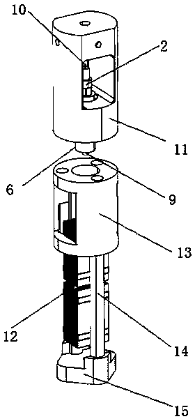
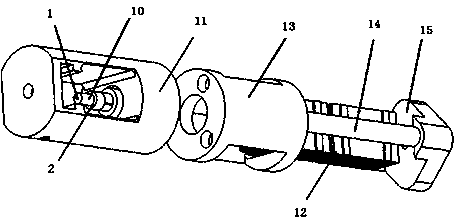
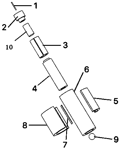
[0019] The invention provides a scanning tunneling microscope structure using motor-scanning head separation technology. The invention improves the existing scanning tunneling microscope to solve the technical problem that the impact of the stepping motor on the scanning head in the existing scanning tunneling microscope leads to the decline in imaging quality. , so that it can effectively prevent thermal drift, electrical fluctuations and other interference factors generated by the motor from affecting the imaging of the scanning head, making the imaging clearer.

[0020] As an embodiment of the present invention, the present invention provides a scanning tunneling microscope structure using motor-scanning head separation technology, including a probe 1, a scanning head, a titanium top seat 11, a piezoelectric stack motor 12, and a scanning tube...


PUM


Abstract

The invention provides a novel scanning tunneling microscope design structure using a motor-scanning head separation technique. A motor and a scanning head are separated, the scanning head is clamped at a guide rail independently by a spring piece, and the motor is responsible for pushing the scanning head to a tunnel current zone; and then the scanning head retreats autonomously. The scanning head is composed of a probe, a probe rack, a scanning tube, a corundum pedestal, and a corundum pipe and the like. Therefore, influences on imaging of the scanning head by interference factors like thermal drift and electric fluctuating caused by the motor can be prevented and thus imaging becomes clear.

Description

technical field [0001] The invention relates to the technical field of scanning tunneling microscopes, in particular to a scanning tunneling microscope structure using a motor-scanning head separation technology. Background technique [0002] Scanning Tunneling Microscope (STM) is an important instrument that uses quantum tunneling effect to observe the surface morphology of samples. Because of its ultra-high real-space resolution ability, it is widely used in material property characterization, electrochemical measurement, biological imaging, etc. science field. Since the STM needs to collect extremely weak current signals during operation, the penetration of any tiny sound or vibration will have a serious impact on the stability of the tunnel junction. The scanning head and the stepping motor of the widely used STM are directly connected, and the interference on the motor (such as thermal drift, electric fluctuation, etc.) will be transmitted to the tunnel current, thereb...

Claims


Application Information

Patent Timeline
Patent Type & Authority Patents(China)
IPC IPC(8): G01Q60/10
CPCG01Q60/10
Inventor 张宇峰王建立袁帅东
Owner SOUTHEAST UNIV
Why Eureka
Try Eureka