Compensation method and device for engine crankshaft signal and automobile

A compensation method and compensation device technology, applied in special data processing applications, instruments, electrical digital data processing, etc., can solve problems such as inaccurate crankshaft tooth period and inaccurate engine system control, so as to improve accuracy and control system stability Effect

Active Publication Date: 2017-07-07
GREAT WALL MOTOR CO LTD
View PDF6 Cites 3 Cited by
  • Summary
  • Abstract
  • Description
  • Claims
  • Application Information

AI Technical Summary

Problems solved by technology

[0004] In view of this, the present invention aims to propose a compensation method for engine crankshaft signals to solve the technical problem of inaccurate control of the entire engine system caused by inaccurate crankshaft tooth periods

Method used


Image

  • Compensation method and device for engine crankshaft signal and automobile
  • Compensation method and device for engine crankshaft signal and automobile
  • Compensation method and device for engine crankshaft signal and automobile

Examples


Embodiment Construction

[0032] The embodiments of the present invention are described in detail below. Examples of the embodiments are shown in the accompanying drawings, in which the same or similar reference numerals indicate the same or similar elements or elements with the same or similar functions. The embodiments described below with reference to the accompanying drawings are exemplary, and are intended to explain the present invention, but should not be construed as limiting the present invention.

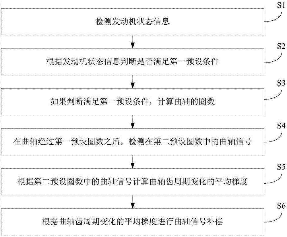
[0033] In theoretical calculations, the angle of each tooth of the crankshaft is fixed, but due to the mechanical error in crankshaft processing and the bending or deformation of the crankshaft teeth that may occur during engine operation, the crankshaft tooth angle is not a completely accurate fixed value. This will result in a certain deviation of the controlled engine angle, which will affect the control accuracy. In order to solve the above-mentioned problems, the present invention proposes a meth...


PUM


Abstract

The invention discloses a compensation method and device for an engine crankshaft signal and an automobile. The compensation method comprises the steps that engine state information is detected; whether a first preset condition is met or not is judged according to the engine state information; if it is judged that the first preset condition is met, the number of circles of a crankshaft is calculated; after the crankshaft rotates by a first preset number of circles, a crankshaft signal in a second preset number of circles is detected; the average gradient of crankshaft tooth cycle change is calculated according to the crankshaft signal in the second preset number of circles; and crankshaft signal compensation is performed according to the average gradient of the crankshaft tooth cycle change. Through the compensation method for the engine crankshaft signal in the embodiment, the accuracy of a crankshaft tooth cycle is improved, therefore, the accuracy of engine speed obtained through calculation according to the crankshaft tooth cycle is improved, and accordingly a control system of an engine is more stable.

Description

Technical field [0001] The invention relates to the technical field of automobiles, and in particular to a method and device for compensating crankshaft signals of an engine, and automobiles. Background technique [0002] The general architecture of the engine control system is to process by collecting the signals of the crankshaft and camshaft, find the actual position of the engine, realize the cylinder judgment, calculate the acceleration and speed of the engine, and finally complete the fuel injection and ignition control. The acceleration and speed calculations of the engine control system in the non-limping mode rely on the crankshaft for calculations. The time the crankshaft rotates one tooth is called the single crankshaft tooth period. If you are using a high-precision type crankshaft, this type of crankshaft has 60 teeth (58 teeth and one missing tooth). One revolution of the crankshaft is 360 degrees, and each tooth rotates 6 degrees. However, due to mechanical error...

Claims


Application Information

Patent Timeline
Patent Type & Authority Applications(China)
IPC IPC(8): G06F17/50
CPCG06F30/17
Inventor 贺庆书龙帆李雷张建彪
Owner GREAT WALL MOTOR CO LTD
Why Eureka
Try Eureka