Slidable socket

A socket and sliding connection technology, which is applied to the parts, electrical components, coupling devices, etc. of the connection device, can solve the problem of not being able to insert two-hole and three-hole plugs at the same time, and achieve the effect of ensuring space occupation and enriching functions.

Pending Publication Date: 2017-07-07
PANZHIHUA UNIV
View PDF13 Cites 3 Cited by
  • Summary
  • Abstract
  • Description
  • Claims
  • Application Information

AI Technical Summary

Problems solved by technology

[0003] The present invention provides a slidable socket to solve the above-mentioned problem that the two-hole and th

Method used


Image

  • Slidable socket
  • Slidable socket
  • Slidable socket

Examples


Example Embodiment

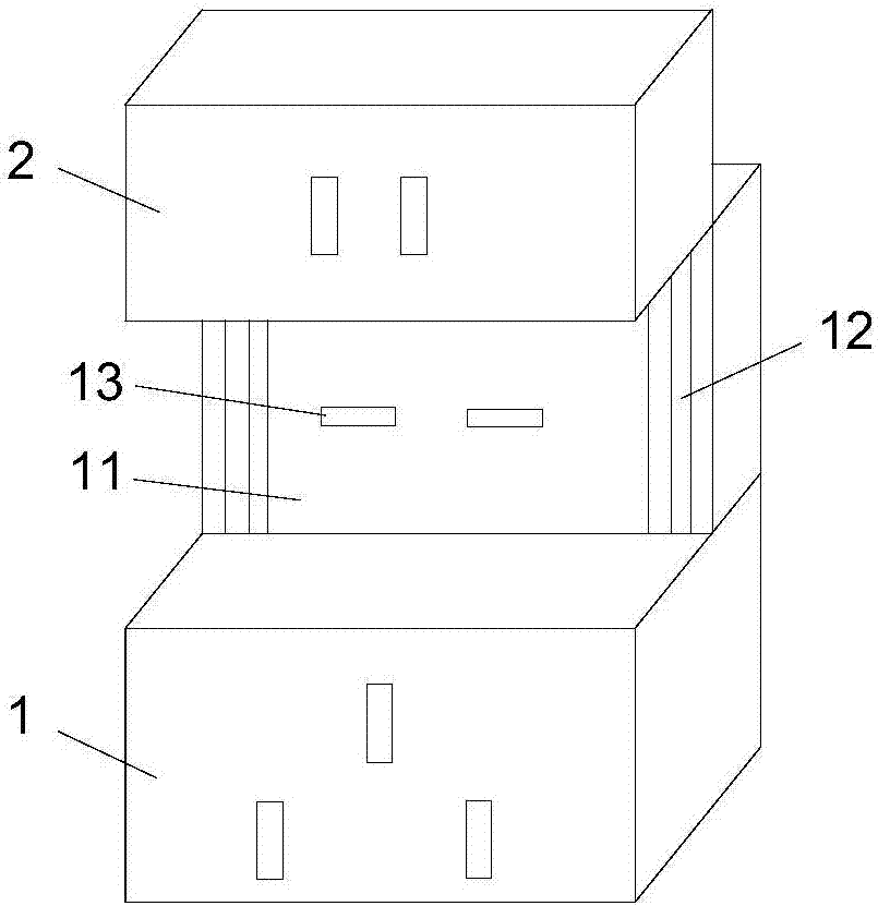
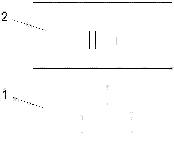
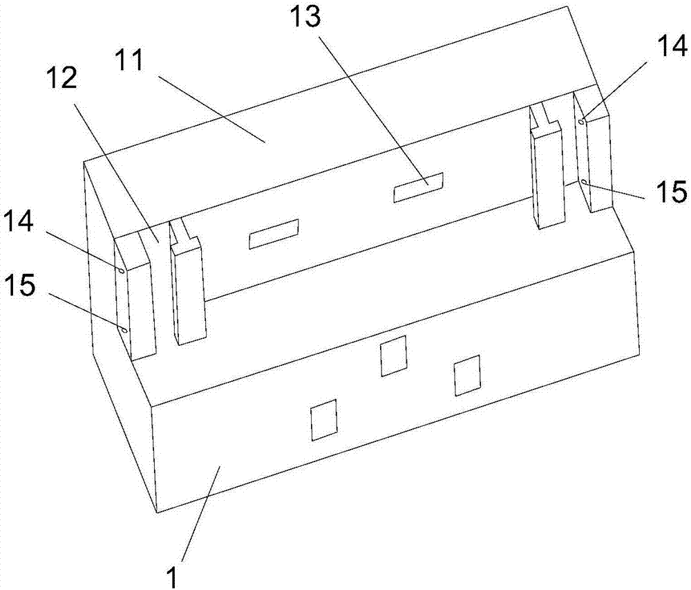
[0017] like Figure 1 to Figure 3 The slidable socket of the present invention shown has a first jack module 1 and a second jack module 2, wherein the first jack module 1 is a three-hole socket structure, and the second jack module 2 is a two-hole socket structure. The first socket module 1 has an upwardly extending backboard 11 , and the second socket module is slidably connected to the backboard 11 through a slide groove 12 provided on the backboard 11 . There are also two USB sockets 13 on the back panel 11, which can be charged by USB.

[0018] like Figure 4 and Figure 5 As shown, the second socket module 2 has a ferrule structure 23 matched with the sliding slot 12 . A transverse telescopic positioning structure is arranged inside the outer wall of the ferrule structure 23 . The telescopic positioning structure has a transversely connected spring 21 and a positioning block 22, and the part of the positioning block 22 protruding from the outer wall of the ferrule str...


PUM


Abstract

The invention relates to a slidable socket which includes a first jack module and a second jack module, the first jack module includes a backboard which extends upwardly, and the second jack module is connected with the backboard in a slidable way via a chute arranged in the backboard. The slidable socket can solve the problem that multiple plugs cannot be plugged into the socket simultaneously due to too small spacing between different jacks, ensures that the occupation space of the socket is minimized, provides USB interfaces, and thus, has more functions.

Description

technical field [0001] The present invention relates to sockets, in particular to slidable sockets. Background technique [0002] The current wall socket is usually a single socket structure, or a structure shared by three holes and two holes. When using the common socket of three holes and two holes, it often happens that after the two holes are plugged in, the three holes may not be inserted because the interval between the three holes and the two holes is too small. At the same time, in the current environment where mobile terminals such as mobile phones and tablet computers are popular, it may often be necessary to charge the mobile terminal through a USB interface. Most of the current wall sockets do not have a USB interface that can provide a fast charging function. Contents of the invention [0003] The invention provides a slidable socket to solve the above-mentioned problem that two-hole and three-hole plugs cannot be inserted at the same time, and provides a USB...

Claims


Application Information

Patent Timeline
IPC IPC(8): H01R13/514H01R27/00
CPCH01R13/514H01R27/00
Inventor 王磊于娟王响张晓霞
Owner PANZHIHUA UNIV
Why Eureka
Try Eureka