Liquid filtering and degassing integration device

A liquid and equipment technology, applied in the field of liquid filtration and degassing integrated equipment, can solve the problem of large space occupation, and achieve the effect of increasing the surface area, ensuring the path and space, and speeding up the filtration speed.

Inactive Publication Date: 2017-11-21
弘毅天承知识产权股份有限公司
View PDF1 Cites 2 Cited by
  • Summary
  • Abstract
  • Description
  • Claims
  • Application Information

AI Technical Summary

Problems solved by technology

[0008] The object of the present invention is: in order to solve the problem that the filtration device and the degassing device of the previous degassing device are independent devices and occupy a large space, the present invention provides an integrated liquid filtration and degassing device

Method used


Image

  • Liquid filtering and degassing integration device

Examples


Embodiment 1

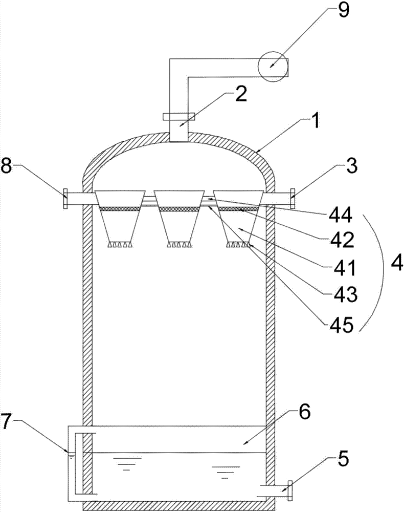
[0030] Such as figure 1 As shown, this embodiment provides an integrated liquid filtration and degassing device, including a tower body 1, a gas outlet 2 on the upper part of the tower body 1, a liquid inlet A3 and a liquid inlet B8, a filter tank assembly 4 inside the tower body, and a tower body 1. The lower liquid storage tank 6, the liquid level gauge 7 connected to the liquid storage tank 6, and the liquid outlet 5 below the tower body. The filter tank assembly 4 includes several filter tanks 41 connected side by side, and the inside of the filter tanks 41 are arranged There is a filter layer 42 , and several nozzles 43 for dispersing liquid are arranged at the bottom of the filter tank 41 , and the liquid inlet A3 and the liquid inlet B8 are respectively connected to the filter tanks 41 at both ends of the filter tank assembly 4 .

[0031] Adjacent filter tanks 41 of the filter tank assembly 4 are connected by hoses 44 , and the hoses 44 are arranged on the upper side of...

Embodiment 2

[0039] Such as figure 1As shown, this embodiment provides an integrated liquid filtration and degassing device, including a tower body 1, a gas outlet 2 on the upper part of the tower body 1, a liquid inlet A3 and a liquid inlet B8, a filter tank assembly 4 inside the tower body, and a tower body 1. The lower liquid storage tank 6, the liquid level gauge 7 connected to the liquid storage tank 6, and the liquid outlet 5 below the tower body. The filter tank assembly 4 includes several filter tanks 41 connected side by side, and the inside of the filter tanks 41 are arranged There is a filter layer 42 , and several nozzles 43 for dispersing liquid are arranged at the bottom of the filter tank 41 , and the liquid inlet A3 and the liquid inlet B8 are respectively connected to the filter tanks 41 at both ends of the filter tank assembly 4 . A certain distance is maintained between the filter tanks 41 of the filter tank assembly 4 and the filter tanks 41 are connected by a hose 44 ,...


PUM


Abstract

The invention discloses a liquid filtering and degassing integration device, which relates to the technical field of degassing devices. The liquid filtering and degassing integration device comprises a tower body, a gas outlet, a liquid inlet A and a liquid inlet B which are in the upper portion of the tower body, a filter tank assembly inside the tower body, a lower liquid storage tank in the tower body, a liquid level gauge connected with the liquid storage tank and a liquid outlet below the tower body, wherein the filter tank assembly comprises a plurality of filter tanks connected side by side, a filter layer is arranged in each filter tank, the bottom of each filter tank is provided with a plurality of spray heads for scattering liquid, and the liquid inlet A and the liquid inlet B are respectively connected with the filter tanks on two ends of the filter tank assembly. A filter apparatus and a degassing apparatus of the traditional degassing apparatus are independent apparatuses and necessarily have respective pumping power, and a temporary storage tank is needed between the filter apparatus and the degassing apparatus when the filter apparatus and the degassing apparatu are connected with each other. The liquid filtering and degassing integration device has the advantages of simplicity in structure, integration of filtering and degassing, and sufficiency in space utilization.

Description

technical field [0001] The invention relates to the technical field of degassing equipment, in particular to an integrated liquid filtration and degassing equipment. Background technique [0002] The liquid contains dissolved gas absorbed from the atmosphere, and the solvent gas in the high-efficiency liquid phase system will cause inaccurate valve action of the infusion pump and disturb the baseline detection line. If the content of air bubbles in the liquid is large, the high-precision constant pressure infusion will also be greatly affected. In addition, dissolved air bubbles will also cause errors in the detection results of refractive index, fluorescence, electrochemical, ultraviolet and other instruments. In particular, for precision analysis, using precision instruments for analysis with high-precision flow management, when reagents, water or other liquids are input into the analytical instrument, if the liquid contains air bubbles, the accuracy of the analytical ins...

Claims


Application Information

Patent Timeline
Patent Type & Authority Applications(China)
IPC IPC(8): B01D19/00
CPCB01D19/0031B01D19/0047
Inventor 赵红昌曹月琴雍海燕
Owner 弘毅天承知识产权股份有限公司
Why Eureka
Try Eureka