Motor stator core laminating tool

A technology of motor stator and lamination tooling, which is applied in electromechanical devices, manufacturing motor generators, manufacturing stator/rotor bodies, etc., can solve the problems of difficult mold taking, difficult disassembly, poor safety, etc., to avoid personnel injury and facilitate disassembly Effect

Inactive Publication Date: 2017-07-07
襄阳中车电机技术有限公司
View PDF0 Cites 3 Cited by
  • Summary
  • Abstract
  • Description
  • Claims
  • Application Information

AI Technical Summary

Problems solved by technology

[0002] At present, the known lamination tooling for stator cores of electric motors has the following disadvantages: ①The core body of the lamination tooling is integral or wedge-shaped. If the gap between the lamination and the stator core punching is large, it cannot satisfy the lamination coefficient of the core and the groove after lamination. Stator core punches are easily deformed after lamination; if the fit gap with the punches is small, it will be difficult to take the mold after lamination, difficult to disassemble after use, and difficult to hoist. Usually, cold pressing or heating the stator core is required. method, which has high work intensity and poor safety; ②The original tooling failed to effectively control the loosening of the teeth of the punching sheet

Method used


Image

  • Motor stator core laminating tool
  • Motor stator core laminating tool
  • Motor stator core laminating tool

Examples


Embodiment Construction

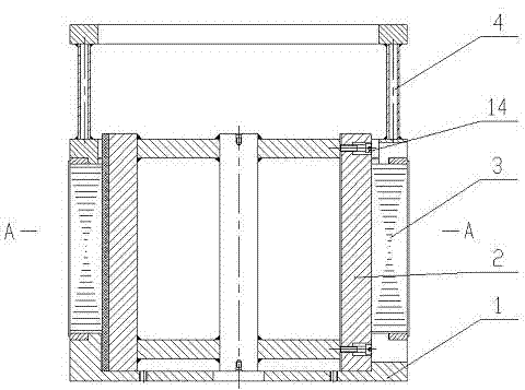
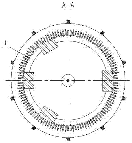
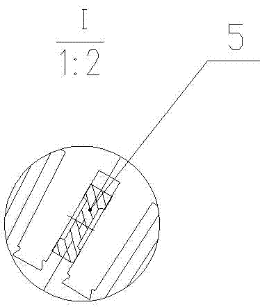
[0016] Such as figure 1 , 2 , 3, 4, 5, and 6, the motor stator core lamination tooling of the present invention mainly includes a base 1, a pressure tire 2, a die 4 and a groove sample block 5; the base 1 is a circular plate with an inner circular hole Seat, on the outer circumference of the base 1, evenly distributed notches are arranged, such as Figure 4 As shown, in order to facilitate positioning welding of the tie bars after the stator core is stacked; the inner diameter of the base 1 matches the outer diameter of the bead 2, and one end of the bead 2 is set in the inner hole of the base 1; the bead 2 It is a cylinder with upper and lower pressure plates 10, and the upper and lower pressure plates 10 are fixed on the cylinder by welding, and a support column 9 is arranged in the center of the press tire 2 along the axial direction, and the upper and lower ends of the support column 9 are fixed on the upper and lower ends. On the pressing plate 10, the upper and lower e...


PUM


Abstract

The name of the present invention is a lamination tooling for motor stator cores, and relates to a tooling used for lamination of motor stator cores. It is mainly to solve the problem that the existing motor stator core lamination tooling cannot meet the requirements of the core lamination coefficient and the unevenness of the groove shape after lamination. question. The present invention includes a pressure tire arranged in the center hole of the base and a pressure die disposed on the other end of the pressure tire, and is characterized in that the pressure tire is a cylindrical body provided with upper and lower pressure plates, and the pressure tire is arranged in the center of the cylindrical body along the axial direction A support column is provided, and the two ends of the support column are respectively fixed on the upper and lower pressure plates, and fixed ribs and movable ribs are arranged on the outer wall of the tire cylinder, and the two ends of the fixed ribs and the movable ribs are respectively fixed on the upper and lower pressure plates. The pressure tire of the present invention has the functions of positioning and tensioning, can ensure the irregularity of the groove shape after the iron core is laminated, and is convenient for hoisting and dismounting;

Description

technical field [0001] The invention relates to a motor stator core lamination tool, in particular to a locomotive generator stator core lamination tool. Background technique [0002] At present, the known lamination tooling for stator cores of electric motors has the following disadvantages: ①The core body of the lamination tooling is integral or wedge-shaped. If the gap between the lamination and the stator core punching is large, it cannot satisfy the lamination coefficient of the core and the groove after lamination. Stator core punches are easily deformed after lamination; if the fit gap with the punches is small, it will be difficult to take the mold after lamination, difficult to disassemble after use, and difficult to hoist. Usually, cold pressing or heating the stator core is required. The traditional method has high work intensity and poor safety; ②The original tooling failed to effectively control the problem of loosening of the teeth of the punching sheet. Cont...

Claims


Application Information

Patent Timeline
Patent Type & Authority Applications(China)
IPC IPC(8): H02K15/02
CPCH02K15/026
Inventor 胡文翠姜承玲曾巍
Owner 襄阳中车电机技术有限公司
Why Eureka
Try Eureka