Stitch welding method for motor core of new-energy automobile

A new energy vehicle and iron core technology, applied in arc welding equipment, welding equipment, welding accessories, etc., can solve problems such as excessive concentration of welding stress, welding strength not meeting the requirements of subsequent processes, adjustment of increasing and decreasing punching, etc., to achieve The effect of reducing pressure and eliminating local burr unevenness

Inactive Publication Date: 2018-11-06
NANTONG TONGDA SILICON STEEL STAMPING TECH CO LTD
View PDF0 Cites 3 Cited by
  • Summary
  • Abstract
  • Description
  • Claims
  • Application Information

AI Technical Summary

Problems solved by technology

[0003] In practice, because one side is thicker and the other is thinner formed by the coil rolling process, the cumulative height deviation after stamping into punched sheets exceeds the allowable value of the length design, and the high point position exceeds the upper difference, and the low point position is lower than the lower difference. , the technical problem that cannot be adjusted by increasing or decreasing punching
[0004] In actual production, after a period of welding (including turnover transportation), the iron core fracture rate is as high as 10%; the welding strength does not meet the requirements of the subsequent process, and the welding stress is too concentrated, which cannot provide customers with high-quality products

Method used


Image

  • Stitch welding method for motor core of new-energy automobile
  • Stitch welding method for motor core of new-energy automobile

Examples


Embodiment Construction

[0026] The present invention is described in further detail now in conjunction with accompanying drawing. These drawings are all simplified schematic diagrams, which only illustrate the basic structure of the present invention in a schematic manner, so they only show the configurations related to the present invention.

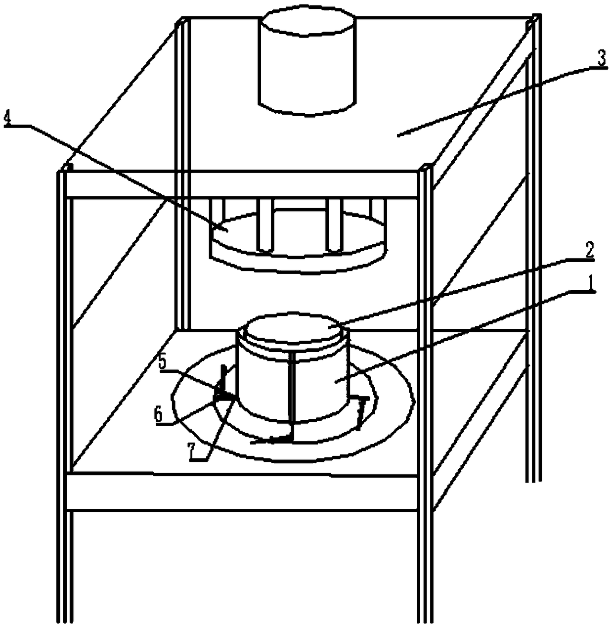
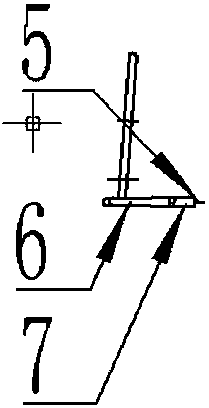
[0027] like Figure 1-2 Shown, a kind of lap welding method of new energy automobile motor core, comprises the following steps:

[0028] A. Weigh the self-riveting iron core 1 made of silicon steel and insert it into the laminated mold 2. When inserting it, it is divided into four sections according to the length of the iron core, and each section is 180 degrees relative to the previous section;

[0029] B. Set the pre-compression pressure on the control panel of the press 3, and the pressure head 4 goes down to perform pre-compression, flatten the riveting point, and reach the inter-sheet pressure;

[0030] C. Reduce the pressure and maintain the pressure; ...


PUM


Abstract

The invention discloses a stitch welding method for a motor core of a new-energy automobile. The stitch welding method comprises the following steps that A, the self-riveted core made from silicon steel is weighed and then is arranged in an overlying mold in a sleeved mode, wherein in the process of arranging the self-riveted core into the overlying mold in the sleeved mode, the core is evenly divided into four sections, and the position of each section is changed by 180 degrees relative to the prior section; B, the pre-pressing pressure is set, and pre-pressing is conducted to press a rivet point flat; C, the pressure is decreased and then is maintained; D, the angle of a tungsten needle and the angle of a welding gun are adjusted; E, process parameters such as the stroke of a press, thegas flow of a gas cylinder and the current of a welding machine are set; F, the pressure of the gas cylinder is checked, and ignition is conducted for trail welding; G, a welding light barrier is placed down to conduct argon arc welding; and H, the pressure is released, the core is taken out, and finally, the length, the appearances of an inner circle and an outer circle of the core, the groove shape uniformity and the appearance of a weld joint are checked. Compared with the prior art, the stitch welding method has the beneficial effects that the weight, the pressure and the length are combined, and the number of punching times of the core is controlled in the operating process, so that the overlying coefficient is ensured, and the overlying quality is ensured.

Description

technical field [0001] The invention belongs to the field of new energy vehicle drive motor core manufacturing and relates to a method for lap welding of new energy vehicle motor cores. Background technique [0002] At present, when the cores of new energy vehicles are stacked and welded, some of them adopt the design of self-riveting buckle points and welding grooves, especially for small-diameter stators and rotors, and the welding grooves are generally designed as W grooves. [0003] In practice, because one side is thicker and the other is thinner formed by the coil rolling process, the cumulative height deviation after punching and lamination exceeds the allowable value of the length design, and the high point position exceeds the upper difference, and the low point position is lower than the lower difference. , the technical problem that cannot be adjusted by increasing or decreasing punching. [0004] In actual production, after a period of welding (including turnove...

Claims


Application Information

Patent Timeline
Patent Type & Authority Applications(China)
IPC IPC(8): B23K9/00B23K9/167B23K9/32
CPCB23K9/0026B23K9/167B23K9/32B23K9/326
Inventor 蒋春萍宋智锋
Owner NANTONG TONGDA SILICON STEEL STAMPING TECH CO LTD
Why Eureka
Try Eureka