Stator string symmetric resistor reversible reversal connection brake control circuit

A technology of reverse braking and control lines, applied in the electrical field, can solve problems such as asymmetry, poor braking effect, and irreversibility

Inactive Publication Date: 2017-07-11
ANHUI JIUNENG INFORMATION TECH
0 Cites 0 Cited by

AI-Extracted Technical Summary

Problems solved by technology

However, the existing reversible reverse braking control circuit has techn...

Abstract

The invention relates to a stator series symmetrical resistance reversible and reverse braking control circuit, which belongs to the field of electric technology, and includes a three-phase power supply, a fuse group, a contactor circuit, a current-limiting resistance circuit, a thermal relay group, and a three-phase asynchronous motor M circuit. It is characterized in that: the three-phase power supply is connected to three knife switches Q through three incoming lines, the three knife switches Q are connected in series with three fuses FR in the fuse group, and the fuse group is connected to the current-limiting resistance circuit The contactor circuit, the input end and the output end of the thermal relay group are respectively connected with the output ends of the three main lines in the current limiting resistance circuit and the three phases of the M circuit of the three-phase asynchronous motor. Adopting the reversible reverse connection braking control circuit designed by the present invention can solve technical problems such as asymmetry, irreversibility, poor braking effect and the like existing in the existing reversible reverse connection braking control circuit technology.

Application Domain

Ac motor stoppers

Technology Topic

ContactorCurrent limiting +9

Image

  • Stator string symmetric resistor reversible reversal connection brake control circuit

Examples

  • Experimental program(1)

Example Embodiment

[0009] The content of the present invention will be further described below in conjunction with the drawings and specific embodiments.
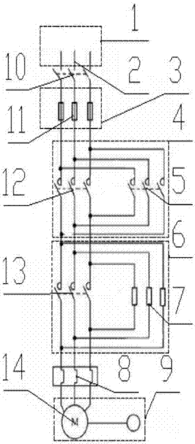
[0010] The structure diagram of a stator series symmetrical resistance reversible reverse connection brake control circuit is as follows figure 1 As shown, a stator string symmetrical resistance reversible reverse connection braking control circuit includes a three-phase power supply 1, a fuse group 3, a contactor circuit 4, a current limiting resistor circuit 6, a thermal relay group 8, and a three-phase asynchronous motor M Circuit 9, characterized in that: the three-phase power supply 1 is connected to the three-blade switch Q10 via three incoming lines 2, the three-blade switch Q10 is connected in series with the three fuses FR11 in the fuse group 3, and the fuse group 3 is connected to The contactor circuit 4 is connected between the current-limiting resistance circuit 6, and the input and output ends of the thermal relay group 8 are respectively connected to the three main line output ends of the current-limiting resistance circuit 6 and the three-phase phase of the M circuit 9 of the three-phase asynchronous motor.
[0011] As a further description of the above technical solution, the three main lines of the contactor circuit 4 are connected to the main contacts B12 of the contactor KM, and three main contacts A5 of the contactor KM are connected in parallel in sequence.
[0012] As a further description of the above technical solution, the three main lines of the current limiting resistor loop 6 are connected to the main contacts C13 of the contactor KM, and three current limiting resistors 7 are connected in parallel in sequence.
[0013] The above are only the preferred embodiments of the present invention, and the protection scope of the present invention is not limited to the above-mentioned embodiments, and all technical solutions under the idea of ​​the present invention belong to the protection scope of the present invention. It should be pointed out that for those of ordinary skill in the art, several improvements and modifications made without departing from the principle of the present invention should also be regarded as the protection scope of the present invention.

PUM

no PUM

Description & Claims & Application Information

We can also present the details of the Description, Claims and Application information to help users get a comprehensive understanding of the technical details of the patent, such as background art, summary of invention, brief description of drawings, description of embodiments, and other original content. On the other hand, users can also determine the specific scope of protection of the technology through the list of claims; as well as understand the changes in the life cycle of the technology with the presentation of the patent timeline. Login to view more.
Why Eureka
Try Eureka