Method and system of controlling asynchronous contactors for a multi-phase electric load

a technology of asynchronous contactor and electric load, applied in the direction of relays, emergency protective arrangements for limiting excess voltage/current, light and heating apparatus, etc., can solve the problems of contactor construction drawbacks, composite materials can be expensive, and contribute to the increase of contactor manufacturing costs, etc., to achieve the effect of reducing mechanical stress

Active Publication Date: 2005-01-20
EATON INTELLIGENT POWER LIMITED
View PDF28 Cites 89 Cited by
  • Summary
  • Abstract
  • Description
  • Claims
  • Application Information

AI Technical Summary

Benefits of technology

The present invention provides a method and apparatus of independently controlling contactors in an asynchronous or multi-stage manner to reduce mechanical stress on an induction motor or other electric power system that overcomes the aforementioned drawbacks and provides a control scheme that is applicable therewith.

Problems solved by technology

This contactor construction has some drawbacks, particularly in high power motor starter applications.
These composite materials can be expensive and contribute to increased manufacturing costs of the contactor.
Other contactors have been designed with complex biasing mechanisms to regulate “blow open” of the contacts under variable fault conditions, but the biasing mechanisms also add to the complexity and cost of the contactor.
Increasing the size of the contact elements, however, requires larger actuating mechanisms, coils, biasing springs, and the like, which all lead to increased product size and increased manufacturing costs.
Additionally, a contactor wherein all the contact assemblies open in unison can result in contact erosion as a result of arcs forming between the contacts during breaking.
When all the contact assemblies or sets of contacts are controlled in unison, a detected abnormal condition, such as a fault condition, in any phase of the three-phase input causes all the contact assemblies to break open because the contact assemblies share a bridge or crossbar.
As a result, the contacts may open at non-ideal current conditions.
This non-zero opening can cause arcing between the contact elements of the second and third contact assemblies causing contact erosion that can lead to premature failure of the contactor.
This unison-controlled construction also has disadvantages associated with the closing of contacts to cause high transient current conduction between a power source and a load.
The closing in unison of all the contacts can cause mechanical torque oscillations that are often negative.
As a result, the windings of a motor as well as the mechanical components of the system are subjected to damaging stresses.
Additionally, the motor circuit protection disconnect (breaker or fusing) may have to be oversized to avoid unwanted, or “nuisance”, tripping by this high transient current.
This is particularly problematic for motor starting applications.
The drawbacks of such an in-unison contactor assembly design can be particularly damaging for motor starting applications.
This superposition of the DC and AC currents can then cause high inrush currents, current imbalances, and strong torque pulsations until the DC current gradually decays with the magnetization time constant of the motor.
The effect is strong torque pulsations and unbalanced currents until the DC transient decays away.
These starting pulsations can cause stress during motor operation and directly lead to wear, increased maintenance costs, and, ultimately, premature motor breakdown.
Torque oscillations or pulsations can be particularly problematic for a motor having its windings arranged in a delta configuration.
Nevertheless, as shown in FIG. 38, standard wye-delta switching remains susceptible, albeit to a lesser degree, to torque pulsations at both the initial wye switch-on, and at the wye-delta switch-over.
It is therefore advantageous to allow the back emf to decay before simultaneously re-closing the contactors to connect the motor windings in delta. However, as shown in FIG. 39, simply allowing the back force, or rotor emf, to decay does not eliminate torque pulsations or oscillations when the contactors are re-closed simultaneously.

Method used


Image

  • Method and system of controlling asynchronous contactors for a multi-phase electric load
  • Method and system of controlling asynchronous contactors for a multi-phase electric load
  • Method and system of controlling asynchronous contactors for a multi-phase electric load

Examples


Embodiment Construction

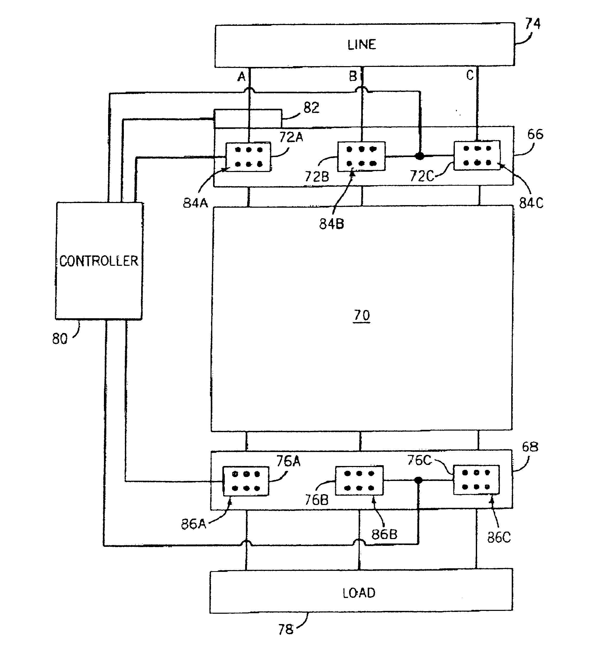
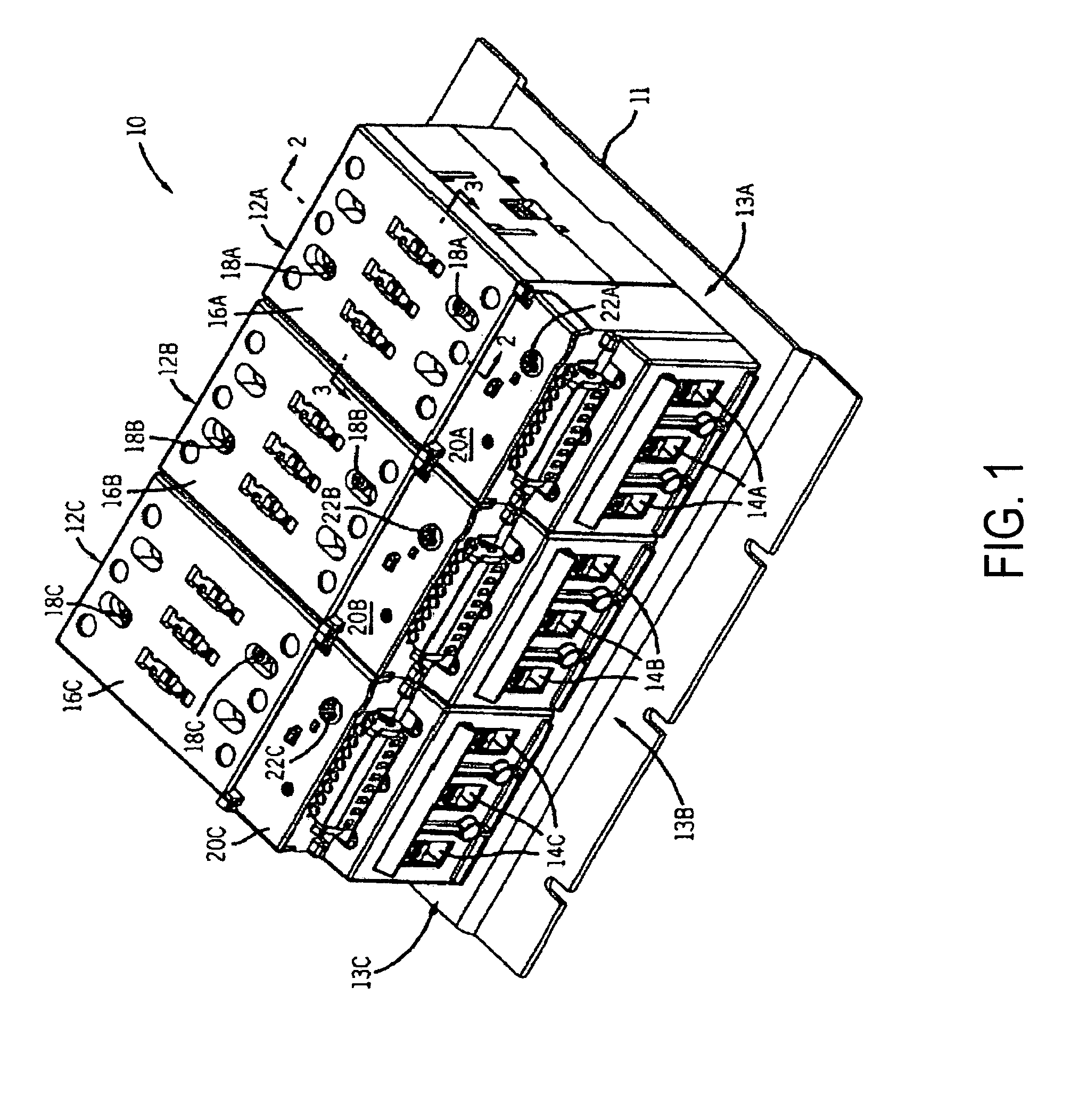
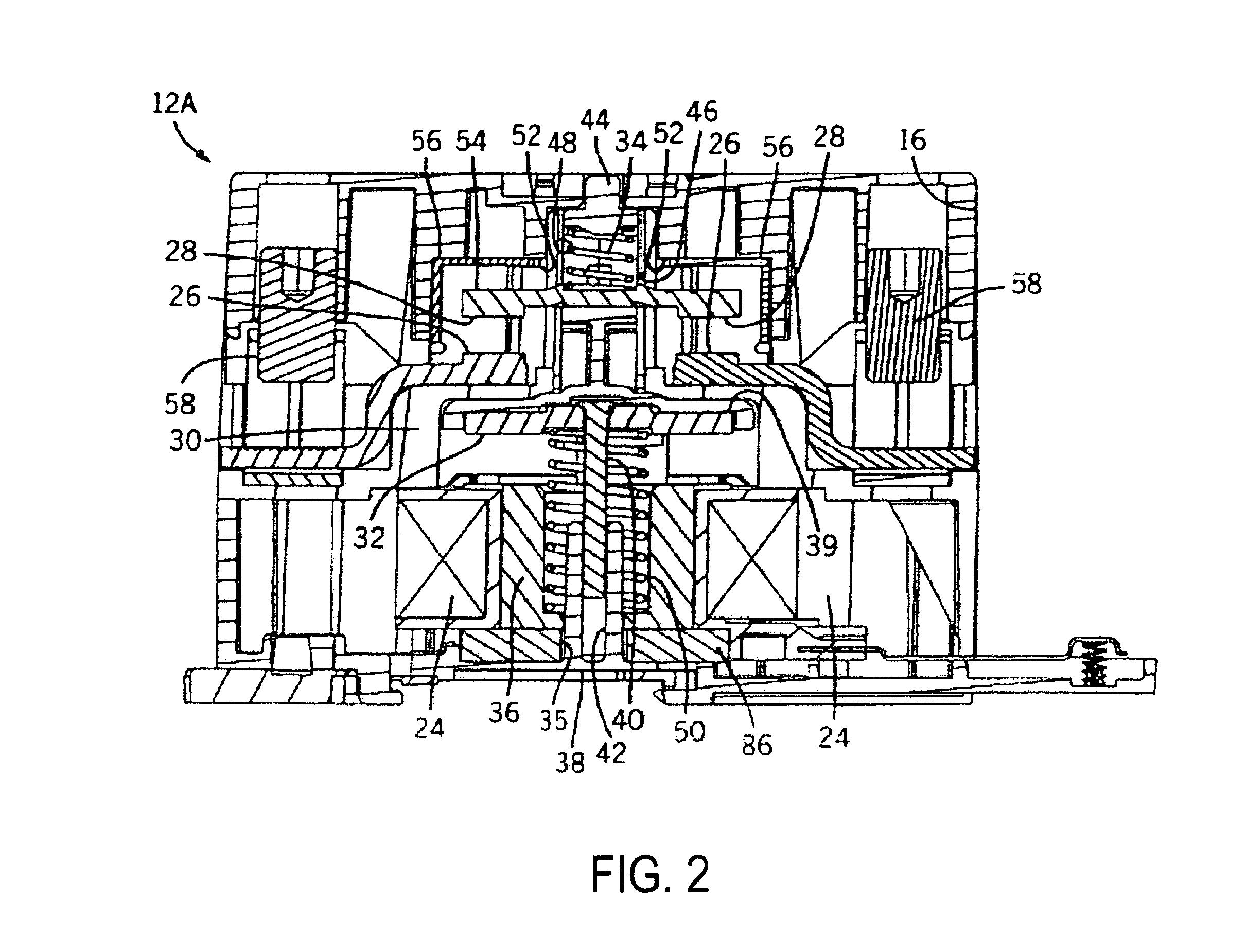
The present invention will be described with respect to an electromagnetic contactor assembly for use in starter applications such as, the switching on / off of a load as well as to protect a load, such as a motor, from current overload, oscillation, and, ultimately, potentially damaging mechanical stresses. The electromagnetic contactor assembly and controls of the present invention are equivalently applicable to heating load contactor assemblies, on-demand modular contactor assemblies, modular large frame contactor assemblies, and the like. The present invention is also applicable with other types of contactor assemblies where it is desirable to reduce contact erosion resulting from arcs during breaking and bounce arcs during making of the contacts. Additionally, the present invention will be described with respect to implementation with a three-phase induction motor; however, the present invention is equivalently applicable with other electrical devices. Furthermore, the present i...


PUM


Abstract

Control of an induction motor is carried out to limit damaging arcing stress and mechanical stresses placed on the control contactor assembly and the induction motor resulting from the simultaneous or synchronous breaking and making of contactors employed to connect the windings of the motor to a power supply. Asynchronously connecting the windings to the power supply via the asynchronous or non-simultaneous closing of the contactors of a modular contactor assembly reduces the potentially damaging transient current, the associated torque oscillations, and mechanical stresses. The present invention is particularly applicable to delta motors that are started with its windings in a star or wye configuration followed by the reconnection of the windings in a delta configuration when the motor is at normal running speed.

Description

BACKGROUND OF THE INVENTION The present invention relates generally to an electrical switching device, and more particularly, to a method and apparatus of asynchronously controlling contactors to reduce mechanical stresses on an induction motor during transition between modes of operation. Typically, contactors are used in starter applications to switch on / off a load as well as to protect a load, such as a motor, or other electrical devices from current overloading. As such, a typical contactor will have three contact assemblies; a contact assembly for each phase or pole of a three-phase electrical device. Each contact assembly typically includes a pair of stationary contacts and a moveable contact. One stationary contact will be a line side contact and the other stationary contact will be a load side contact. The moveable contact is controlled by an actuating assembly comprising an armature and magnet assembly which is energized by a coil to move the moveable contact to form a br...

Claims


Application Information

Patent Timeline
Patent Type & Authority Applications(United States)
IPC IPC(8): H01H9/40H01H9/56H01H50/22H02P1/32H02P25/18
CPCH01H9/40H01H9/563H02P25/18H02P1/32H01H50/22H01H50/002
Inventor KINSELLA, JAMES J.UNSWORTH, PETER J.ZHOU, XINWIELOCH, CHRISTOPHER J.LITTLE, MICHAEL T.
Owner EATON INTELLIGENT POWER LIMITED
Why Eureka
Try Eureka