Portable test tube stand

A test tube rack and portable technology, which is applied in the field of portable test tube racks, can solve the problems of single function of test tube racks, and achieve the effects of improving practicability, rational design, and easy distinction

Inactive Publication Date: 2017-07-14
HUBEI POLYTECHNIC INST
View PDF7 Cites 6 Cited by
  • Summary
  • Abstract
  • Description
  • Claims
  • Application Information

AI Technical Summary

Problems solved by technology

[0003] The technical problem to be solved by the present invention is to overcome the defect of the single function of the existing test tube rack and provide a convenient test tube rack

Method used


Image

  • Portable test tube stand
  • Portable test tube stand

Examples


Embodiment

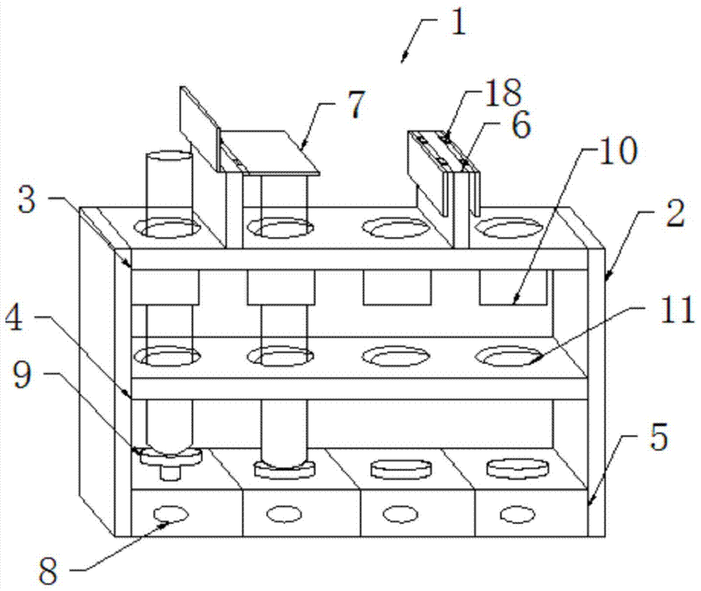
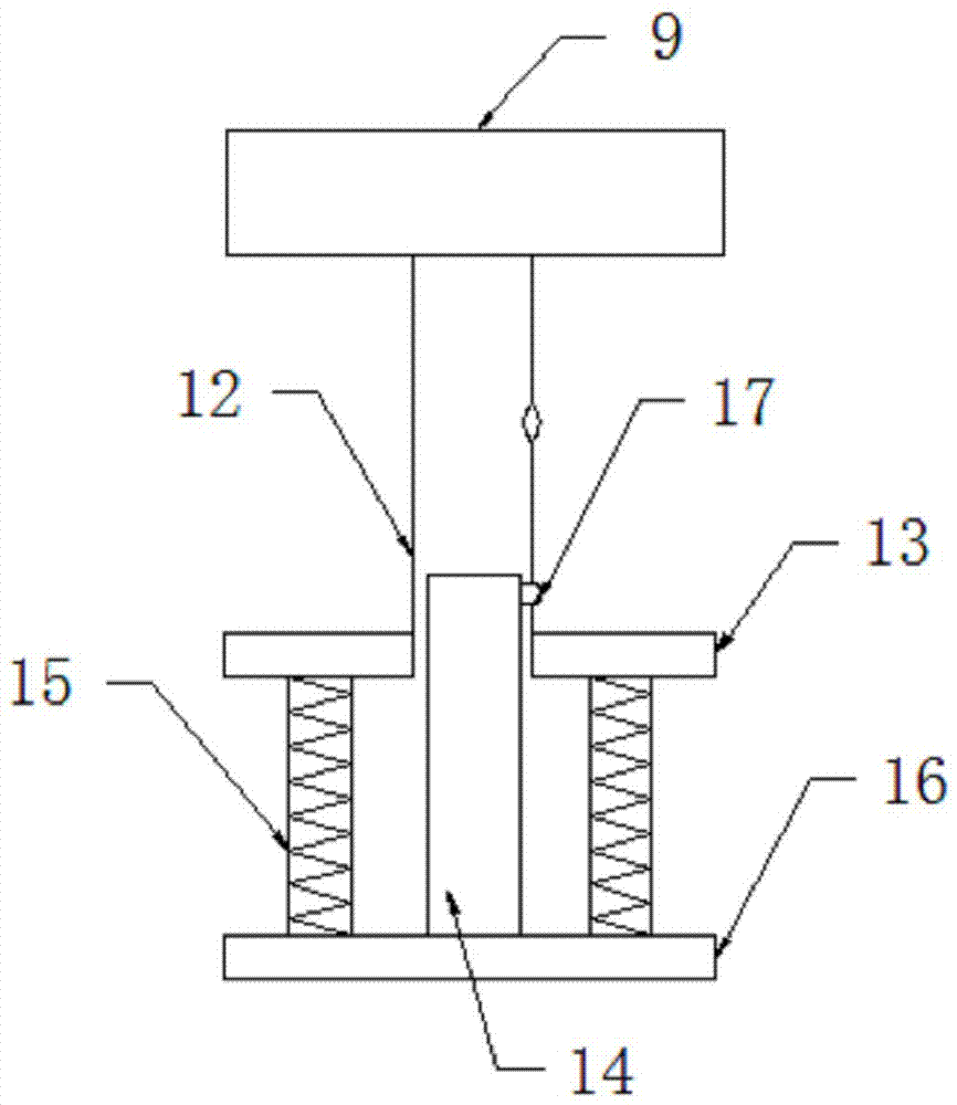
[0016] Such as Figure 1-2 As shown, a portable test tube rack includes a test tube rack body 1, a frame 2 is arranged on the outside of the test tube rack body 1, an upper fixing plate 3 is arranged on the inner side of the upper end of the frame 2, and a middle fixing plate 4 is arranged on the inner side of the middle part of the frame 2, and the frame 2 The bottom is provided with a base plate 5, and the upper fixed plate 3 and the middle fixed plate 4 are provided with a number of placement holes 11 at the corresponding positions, and a cover bracket 6 is arranged between the two placement holes 11 on the upper fixed plate 3, and the cover plate Both sides of the upper end of the support 6 are provided with a cover plate 7, on the base plate 5 and positioned at the corresponding bottom of the placement hole 11, several bases 9 are provided, one side of the base plate 5 is provided with the same number of buttons 8 as the base 9, and the bottom of the base 9 is provided wit...


PUM


Abstract

The invention discloses a portable test tube stand. The portable test tube stand comprises a test tube stand body, wherein a framework is arranged at the outer side of the test tube stand body; an upper fixed plate is arranged at the inner side of the upper end of the framework; a middle fixed plate is arranged at the inner side of the middle of the framework; a bottom plate is arranged at the bottom of the framework; cover plate brackets are arranged between two placement holes on the upper fixed plate; cover plates are arranged at two sides of the upper ends of the cover plate brackets; buttons with the quantity which is the same as that of bases are arranged at one side of the bottom plate; sleeves are arranged at the lower sides of the bases; a buckle is arranged at one side of each sleeve; a connecting plate is arranged at the lower end of each sleeve; resetting springs are arranged at two ends below each connecting plate; fixed plates are arranged at the bottoms of the resetting springs; inner sleeves are arranged at the upper sides of the fixed plates; cover plates are arranged at the upper side of the test tube stand and has an effect of shielding a test tube opening, so that the volatilization of a reagent is stopped and impurities are prevented from entering test tubes; an ejection device and a button combination are arranged at the bottom of the test tube stand and ejection is controlled through the buttons, so that the test tubes are rapidly and conveniently taken out and are not easily taken by mistake.

Description

technical field [0001] The invention relates to a portable test tube rack, which belongs to the technical field of experimental equipment. Background technique [0002] The test tube rack is the most basic experimental instrument in the chemical laboratory used to place (sometimes the test tube can also be placed on the test tube rack to observe the phenomenon of an experiment) and dry the test tube. Columns and small holes, if there are small holes, the test tubes can be placed vertically for use or to continue to observe the reaction. The laboratory is easy to cause reagents to volatilize, especially when doing some toxic and volatile chemical experiments. If the test tube mouth is not covered, it is easy to cause reagents to volatilize. After being inhaled by the experimenters, they will harm their health, and in serious cases directly threaten personnel life. Contents of the invention [0003] The technical problem to be solved by the present invention is to overcome...

Claims


Application Information

Patent Timeline
IPC IPC(8): B01L9/06
CPCB01L9/06
Inventor 郑园
Owner HUBEI POLYTECHNIC INST
Why Eureka
Try Eureka