Combine harvester

A technology for combine harvesters and harvesting devices, which is applied in the directions of harvesters, cutters, agricultural machinery and implements, etc., can solve the problems of the harvesting device protruding into the ground, poor operability of the combine harvester, and reduced harvesting efficiency.

Active Publication Date: 2010-06-09
ISEKI & CO LTD
View PDF7 Cites 0 Cited by
  • Summary
  • Abstract
  • Description
  • Claims
  • Application Information

AI Technical Summary

Problems solved by technology

[0006] However, in the case of such a structure, for example, in the harvesting driving process, when the combine harvester is necessary to operate the steering switch due to deviation from the grain stalk, if the operator makes a mistake and operates the harvesting device lifting switch, the harvesting device will Descending against the operator's will, causing the harvesting device to protrude into the ground
That is, in the above-mentioned prior art, there is a problem that the operability of the combine harvester is very poor and the efficiency of the harvesting work is reduced.

Method used


Image

  • Combine harvester
  • Combine harvester
  • Combine harvester

Examples


Embodiment Construction

[0029] Embodiments of the invention shown in the drawings will be described below.

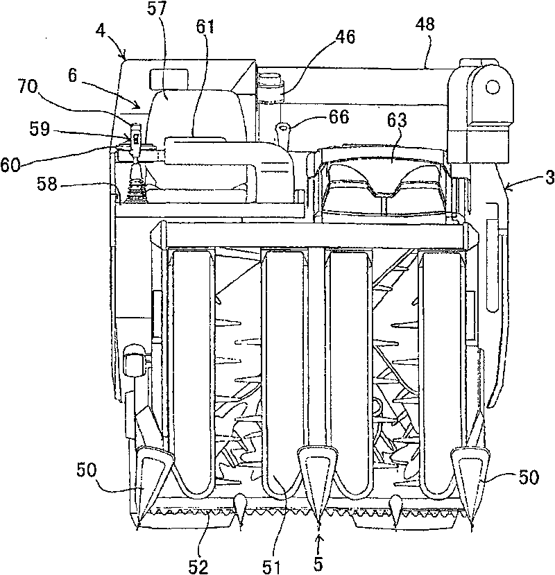
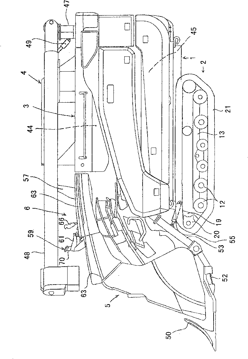
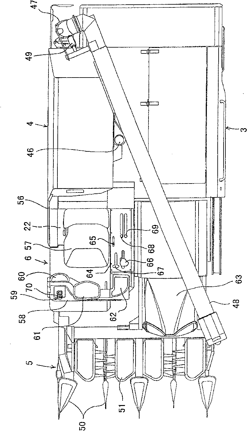
[0030] First, according to figure 1 , figure 2 , image 3 The overall structure of the combine equipped with the control lever of this invention is demonstrated. figure 1 is the front view of the combine harvester, figure 2 is the side view of the combine harvester, image 3 It is a top view of the combine harvester.

[0031] The combine harvesting mechanism is such that a traveling device 2 is provided on the lower side of the vehicle body 1, a threshing device 3 and a grain storage device 4 are arranged side by side on the upper side of the vehicle body 1, and a reaping device 3 is freely installed in front of the threshing device 3. The device 5 is provided with an operation part 6 on the front side of the grain accumulating device 4 .

[0032] Figure 4 , Figure 5 The structure of the above-mentioned traveling device 2 is shown.

[0033] The middle portions of the front swing a...


PUM


Abstract

The invention relates to a united reaping machine which can be excellently operated by fingers of a hand holding an operating bar to, with less error operations, adjust height of a reaping device, height of the machine and gesture of the machine body, and to perform the steering united reap of the machine body, and which can improve the efficient of reaping work via the united reaping machine. A face at front side of a holding part (70) of the operating bar (59) is provided in parallel with an ascending switch (SW1) and a descending switch (SW2) both for ascending and descending operations ofthe reaping device in up and down directions; a position between the ascending switch (SW1) and the descending switch (SW2) is provided with an error operation preventing projection part (71) which projects more than pressing operational surfaces of the switches. In addition, the same projection part (73) is also provided at the position between a machine height ascending switch (SW3) and a machine height descending switch (SW4) which are provided on the surface of left side of the holding part (70).

Description

technical field [0001] The present invention relates to combine harvesters. Background technique [0002] Conventionally, an operation lever that raises the harvesting device by operation in the front-rear direction and turns the vehicle body by operation in the left-right direction is provided on the control unit provided on the vehicle body of the combine harvester. [0003] Various operating switches are provided on the grip portion of the operating lever. As this prior art, as disclosed in Patent Document 1 (Patent Document 1: Japanese Unexamined Patent Application Publication No. 2000-71801), there is provided a forward and backward movement on the grasping portion of the operating lever provided on the operating portion of the construction machine. The switch for shifting, the acceleration switch and deceleration switch for driving shift, and the technology that the switch for siren is installed on the side of the grip part. These switches are arranged within a range...

Claims


Application Information

Patent Timeline
Patent Type & Authority Patents(China)
IPC IPC(8): A01D41/127
Inventor 福地和宪冲本章高木慎石川道男渡边均西崎宏指原宏彦冈崎秀范山本次郎
Owner ISEKI & CO LTD
Why Eureka
Try Eureka