
Stamping die slanted blanking device capable of being replaced rapidly

A stamping die and oblique punching technology, which is applied in the field of oblique punching devices, can solve the problems of labor-intensive replacement, labor-intensive time-consuming, punch wear and other problems, and achieve the effect of improving efficiency and reducing costs

Inactive Publication Date: 2017-07-14
NINGBO SHUANGLIN AUTO PARTS
View PDF7 Cites 3 Cited by
  • Summary
  • Abstract
  • Description
  • Claims
  • Application Information

AI Technical Summary

Problems solved by technology

The axis of the hole or groove of complex curved surface sheet metal products is required to be orthogonal to the curved surface, such as the runner hole of the window guide rail of the car door, so the stamping die must be punched obliquely with an oblique punching device; after the stamping die has been running for a period of time , the punch of the oblique punch will be worn out, and it is necessary to regularly update and replace the worn oblique punching device; due to structural reasons, the oblique punching device of the prior art needs to disassemble the entire stamping die from the punching machine before it can be replaced, resulting in The replacement work is labor-intensive, low in efficiency, and high in cost. Therefore, the prior art has the problems and deficiencies of labor-intensive, time-intensive, low in efficiency, and high in cost.

Method used


Image

  • Stamping die slanted blanking device capable of being replaced rapidly
  • Stamping die slanted blanking device capable of being replaced rapidly

Examples


Embodiment Construction

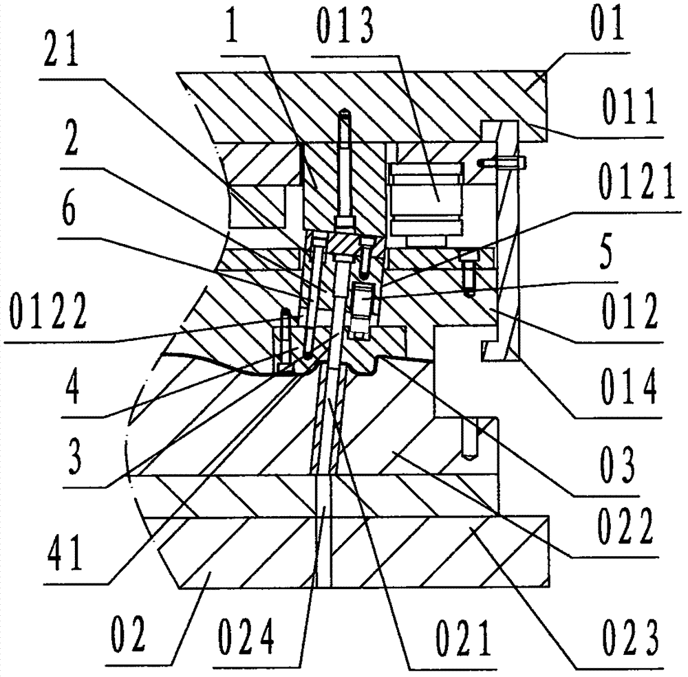
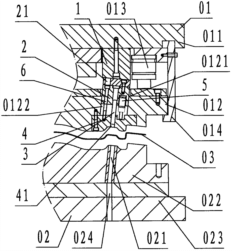
[0023] refer to Figure 1 ~ Figure 2 , a rapidly replaceable stamping die oblique punching device of the present invention, comprising a stamping block 1, a punch carrier block 2, a punch 3, a punch guide block 4, a punch spring 5, a limit bolt 6 and a binder plate 012, wherein: the stamping block 1 is a rectangular block-shaped steel member in a top view, the bottom of the stamping block 1 is provided with a slope inclined from left to right, which is called a stamping slope, and the center of the bottom of the stamping block 1 is provided with The circular step through hole in the up and down direction, small up and big down is called the counterbore of the pressing block;

[0024] The punch 3 is a cylindrical rod-shaped steel component;

[0025] The punch block 2 is a rectangular block-shaped steel member, and the punch 3 is coincidently connected with the central axis of the punch block 2 along the up and down direction, wherein the upper part of the punch 3 is fixed in t...


PUM


Abstract

The invention discloses a stamping die slanted blanking device capable of being replaced rapidly. The stamping die slanted blanking device comprises a stamping block (1), a male die carrying block (2), a male die (3), a male die guiding block (4), a male die spring (5), a limiting bolt (6) and a material pressing plate (012). The male die adopted by the invention protrudes out of the lower face of the male die carrying block provided with a limiting counter bore. The male die guiding block is provided with a guiding hole. An oblique sliding groove is formed in the upper face of the material pressing plate. The stamping block protrudes out of the lower face of an upper die carrying plate. The male die carrying block is slidably located in the oblique sliding groove of the material pressing plate. The male die guiding block is fixed to the lower face of the material pressing plate. The male die spring is located between the male die carrying block and the male die guiding block. The limiting bolt is connected between the male die carrying block and the male die guiding block through a limiting counter bore hook. The lower portion of the male die is slidably located in the guiding hole. According to the technical scheme, the male die carrying block and the male die can be rapidly replaced only by detaching the material pressing plate, so that the purposes of saving work, saving time, improving efficiency and reducing cost of periodic replacement of the stamping die slanted blanking device are achieved.

Description

technical field [0001] The invention relates to an oblique punching device, in particular to a rapidly replaceable oblique punching device for a stamping die used to obliquely punch sheet metal products. Background technique [0002] The stamping direction of the stamping die is divided into longitudinal, transverse and oblique directions. The so-called longitudinal direction is along the opening and closing direction of the stamping die, the so-called transverse direction is the direction orthogonal to the longitudinal direction, and the so-called oblique direction is the direction between the longitudinal direction and the transverse direction. direction. The axis of the hole or groove of complex curved surface sheet metal products is required to be orthogonal to the curved surface, such as the runner hole of the window guide rail of the car door, so the stamping die must be punched obliquely with an oblique punching device; after the stamping die has been running for a pe...

Claims


Application Information

Patent Timeline
Patent Type & Authority Applications(China)
IPC IPC(8): B21D37/04B21D37/10B21D37/12
CPCB21D37/04B21D37/10B21D37/12
Inventor 杨桂林王彬覃杨良
Owner NINGBO SHUANGLIN AUTO PARTS
Learn More