New energy automobile charging interface safe in power supply and charging device

A new energy vehicle and charging interface technology, which is applied in the direction of electric vehicle charging technology, electric vehicles, parts of connecting devices, etc., can solve the problems of reduced service life of charging lines, easy damage of charging plugs, casualties and other problems, and prevent charging accidents The effect of termination, improvement of connection stability, and reduction of electric shock accidents

Active Publication Date: 2017-07-14
泰州市海通资产管理有限公司
3 Cites 15 Cited by

AI-Extracted Technical Summary

Problems solved by technology

[0002] With the emergence of electric vehicles, the use of charging piles for electric vehicles has increased. When users use the existing electric vehicle charging piles to charge electric vehicles, they plug the charging plug directly into the socket for charging. If it is loose, there will be poor contact, and because there is a large current flowing through the socket, the charging plug is easily damaged. When the charging pile is charging the electric vehicle, pulling out the charging gun will cause a safety accident, causing casualties, If the device is damaged or even causes a fire, in order to avoid safety accidents, it is necessary to lock the charging gun during the charging process and unlock it ...

Method used

1. Vertically set the rotating shaft in the wire-receiving cavity, the top of the rotating shaft is connected with the power of the wire-receiving motor, the circumferential direction of the rotating shaft is fixedly provided with a wire-receiving reel, and the charging wire is coiled on the reel, so as to realize automatic wire-receiving Work, reduce staff labor, improve work efficiency.
2. establish connecting block by charging gun head, connecting block right side end face is provided with protruding block, protruding block outer side rotates and cooperates to connect rotating sleeve, and rotating sleeve right side inner wall surrounds and establishes annular groove, and in annular groove, rotates and cooperates to connect An annular protruding ring block fixedly connected to the inner side of the right edge of the protruding block, an internal thread cavity is provided in the rotating sleeve on the right side of the protruding block, and a left end face is fixedly connected to the right end face of the protruding block in the internal thread cavity Charging column, a charging chute is provided in the right end surface of the charging column, guide grooves are symmetrically provided on the upper and lower inner walls of the charging chute, conductive holes are provided on the left inner wall of the charging chute, and the charging mobile block is slid and connected in the charging chute, and the car interface is provided by The base and the externally threaded protruding block fixed on the left side of the base to cooperate with the rotating sleeve can prevent the direct exposure of the conductive sheet, reduce the occurrence of electric shock accidents, improve the stability of the connection, and prevent accidental termination of charging.
Wherein, described external thread protruding block 72 left side end faces are provided with plug-in groove 73, described plug-in groove 73 right side inner walls are fixedly provided with convex block 74, described convex block 74 left side end faces There is a connection pin 741, so as to realize the screw locking connection, and prevent loosening and power failure caused by accidental touc...

Abstract

The invention discloses a new energy automobile charging interface safe in power supply and a charging device. The charging device comprises a charging pile and the automobile interface. A take-up cavity is formed in the charging pile. An operating groove is formed in the outer end face, on the right side of the take-up cavity, of the charging pile. A through hole is formed between the operating groove and the take-up cavity. A first sliding groove with the top communicating with the take-up cavity is longitudinally formed in the inner bottom wall of the right side of the take-up cavity. A second sliding groove is transversely formed in the middle of the first sliding groove in a penetrating mode and communicates with the first sliding groove. A rotating shaft is longitudinally arranged in the take-up cavity. The top of the rotating shaft is connected with a take-up motor in a power fit mode. A take-up reel is fixedly and circumferentially arranged on the rotating shaft. A charging line is wound on the take-up reel. A charging gun is arranged in the operating groove. A plug used for being in plugging fit with the through hole is arranged on the left side end face of the charging gun. The left side end face of the plug is fixedly connected with the charging line. A connecting block is arranged in the charging gun. A protruding block is arranged on the right side end face of the connecting block. The charging device is simple in structure, convenient to operate, stable in connection and high in safety.

Application Domain

Technology Topic

Image

  • New energy automobile charging interface safe in power supply and charging device
  • New energy automobile charging interface safe in power supply and charging device
  • New energy automobile charging interface safe in power supply and charging device

Examples

  • Experimental program(1)

Example Embodiment

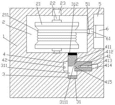
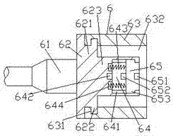
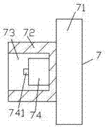
[0023] Such as Figure 1-Figure 8 As shown, the charging interface and charging device for a new energy vehicle with safe power supply of the present invention includes a charging pile 1 and an automobile interface 7. The charging pile 1 is provided with a wire receiving cavity 2 on the right side of the wire receiving cavity 2 An operating slot 5 is provided in the outer end surface of the charging pile 1, a through hole 51 is provided between the operating slot 5 and the wire receiving cavity 2, and the inner bottom wall on the right side of the wire receiving cavity 2 is longitudinally provided with a top The first chute 3 connected to the wire take-up cavity 2 is provided with a second chute 4 transversely through the middle position of the first chute 3 and is connected to the first chute 3, and the retractable A rotating shaft 22 is arranged longitudinally in the wire cavity 2, and the top of the rotating shaft 22 is dynamically connected to the wire take-up motor 23. The rotating shaft 22 is fixedly provided with a wire take-up reel 21 in the circumferential direction. There is a charging cable 211, the operating slot 5 is provided with a charging gun head 6, and the left end surface of the charging gun head 6 is provided with an installation plug 61 for mating with the through hole 51. The side end surface is fixedly connected to the charging cable 211, the charging gun head 6 is provided with a connecting block 62, the right end of the connecting block 62 is provided with a protruding block 621, and the outer side of the protruding block 621 is rotatably connected with The rotating sleeve 63 has an annular groove 631 surrounding the inner wall on the right side of the rotating sleeve 63. The annular groove 631 is rotatably connected with an annular convex ring block 622 whose inner side is fixedly connected with the right edge of the protruding block 621. , The rotating sleeve 63 on the right side of the protruding block 621 is provided with an internal threaded cavity 632, and the internal threaded cavity 632 is provided with a charging post fixedly connected to the left end surface and the right end surface of the protruding block 621 623. The charging chute 64 is provided with a charging chute 64 in the right end surface of the charging column 623. The inner walls of the upper and lower sides of the charging chute 64 are symmetrically provided with guide grooves 641, and the left inner wall of the charging chute 64 is provided with a conductive hole 642. A charging moving block 65 is slidably connected in the charging chute 64, and the car interface 7 is fixedly arranged on the left end surface of the base 71 by a base 71 and an external thread for mating connection with the rotating sleeve 63 The protruding block 72 is composed.
[0024] Wherein, the upper and lower sides of the left side of the charging movable block 65 are symmetrically provided with guide blocks 653 that extend into the guide groove 641 and are slidably connected, and the right end surface of the charging movable block 65 is provided with a power connection hole 651, so A conductive pin 652 is provided in the left end surface of the charging moving block 65, and the inner wall of the charging chute 64 on the upper and lower sides of the conductive hole 642 is symmetrically provided with a sink groove 644, and the sink groove 644 is connected to the charging moving block 65. A top pressure spring 643 is provided between the left end surface, so as to isolate the personnel from the power supply terminal and prevent accidental electric shock.
[0025] Wherein, an insertion groove 73 is provided in the left end surface of the male threaded protrusion block 72, a convex block 74 is fixed on the right inner wall of the insertion groove 73, and the left end surface of the convex block 74 is provided with a connection Electric needle 741, so as to achieve a threaded locking connection, to prevent accidental contact causing looseness and power failure.
[0026] Wherein, the first sliding groove 3 is provided with a first sliding block 31, the top end of the first sliding block 31 is provided with an elastic wear pad 312 opposite to the bottom end of the take-up reel 21, the first The sliding block 31 is provided with a through groove 311, an inclined slide groove 3111 is provided on the upper left side of the through groove 311, and a power supply pin 42 is provided on the inner wall of the second slide groove 4 on the left side of the first slide groove 3. A second sliding block 41 is slidably connected to the second sliding groove 4 on the right side of the first sliding groove 3, and a threaded hole 412 is provided inside the right side of the second sliding block 41. The threaded hole 412 is threaded. The right end of the screw 413 is rotatably connected with the telescopic motor 414, the left end of the second sliding block 41 extends into the through groove 311, and the end surface is provided with a power supply connection hole 414, The upper left end of the second sliding block 41 is provided with an inclined surface portion 411 that is pressed and slidingly fitted with the inclined surface sliding groove 3111, so as to realize automatic power off and power supply connection, and prevent electric shock accidents caused by arc generated during plugging and unplugging.
[0027] Wherein, the power supply contact hole 415 and the conductive hole 642 are electrically connected to both ends of the charging wire 211 respectively.
[0028] In the initial state, the second sliding block 41 is located in the second sliding groove 4 on the right side of the first sliding groove 3, and the right end surface of the second sliding block 41 abuts against the inner wall of the second sliding groove 4 on the right side. The bottom end surface of the sliding block 31 abuts against the bottom end surface of the first chute 3, and at the same time, the inclined surface 411 abuts against the inclined chute 3111. At this time, the elastic wear pad 312 on the top end of the first sliding block 31 is in contact with the wire take-up cavity 2. The inner bottom wall is on the same horizontal plane, so that the elastic wear pad 312 is far away from the bottom end surface of the take-up reel 21 at the maximum distance. At the same time, the charging gun head 6 is completely located in the operation slot 5, and the plug 61 is completely inserted and connected with the through hole 51. When the charging cable 211 is coiled on the take-up reel 21 to the greatest extent, at the same time, the charging moving block 65 in the charging gun head 6 is forced by the pressing spring 643 to move the charging moving block 65 to the rightmost position of the charging chute 64. At this time, the conductive pin 652 on the left end surface of the charging movable block 65 is far away from the conductive hole 642 to the greatest extent.
[0029] When charging is needed, first pull the charging nozzle 6 in the operating slot 5 to move the charging nozzle 6 to the left side of the car interface 7. At this time, pull the charging nozzle 6 toward the car interface 7 until Such as Figure 4 As shown, the inner wall of the rotating sleeve 63 abuts against the outer wall of the externally threaded protrusion 72. At this time, the rotating sleeve 63 makes the externally threaded protrusion 72 gradually screw into the rotating sleeve 63, and at the same time, the rotating sleeve 63 rotates and gradually drives the charging column 623 extends into the socket 73 until Figure 5 The electrical connection pin 741 shown is fully inserted into the electrical connection hole 651, and at the same time, the right end surface of the charging movable block 65 abuts against the left end surface of the convex block 74, and then the rotating sleeve 63 continues to rotate, so that the rotating sleeve 63 continues to drive the charging column 623 Move toward the insertion slot 73. At this time, the charging movable block 65 receives the pressing force of the convex block 74, so that the charging movable block 65 overcomes the elastic pressing force of the pressing spring 643 and moves toward the left of the charging chute 64 in the direction of the guide groove 641. The side inner wall moves, and at the same time, the convex block 74 gradually extends into the charging chute 64 until Image 6 The conductive pin 652 shown is completely inserted into the conductive hole 642. At this time, the left end surface of the charging movable block 65 abuts against the left inner wall of the charging chute 64, and at the same time, the pressing spring 643 is completely retracted into the sink 644. The right end surface of the sleeve 63 abuts against the left end surface of the base 71, so that the charging gun head 6 and the car interface 7 complete the locked charging connection, and then the screw 413 is controlled by the telescopic motor 414 to rotate, and the screw 413 drives the second sliding block 41 along the first The second sliding groove 4 slides to the left, and when the second sliding block 41 slides to the left, the inclined surface 411 and the inclined sliding groove 3111 slide and press to fit, so that the first sliding block 31 moves upward against its own gravity until the inclined surface 411 When sliding away from the inclined sliding groove 3111, at this time, the upper and lower side walls of the second sliding block 41 are respectively slidingly connected with the upper and lower inner walls of the through groove 311, and at the same time, the elastic wear pad 312 elastically abuts against the bottom end surface of the take-up reel 21, so that the receiving The wire reel 21 cannot continue to pay off, to prevent the charging wire 211 from being pulled out excessively during the charging connection, which may cause people to step on and trip over people. Continue to control the rotation of the telescopic motor 414 to make the left end of the second sliding block 41 and The inner wall of the second chute 4 on the right side of the first chute 3 abuts, at this time, the conductive hole 642 is completely inserted into the power supply connection hole 415, such as Figure 7 The charging and power supply connection is completed as shown; when the wire needs to be taken up, the telescopic motor 414 is first controlled to drive the screw 413 to reverse until the second sliding block 41 returns to the initial position. During this process, the first sliding block 31 is elasticized by the elastic wear pad 312 Force and its own gravity, slide into the bottom position of the first chute 3 again. At this time, the power supply connection hole 415 is far away from the power supply pin 42 to the greatest extent. Then, the charging gun head 6 is completely connected to the car interface 7 by rotating the rotating sleeve 63 At this time, the charging moving block 65 is subjected to the elastic pressing force of the pressing spring 643, so that the charging moving block 65 is moved to the rightmost position of the charging chute 64 again. At the same time, the conductive pin 652 is far away from the conductive hole 642 to the greatest extent, and then The rotation of the rotating shaft 22 is controlled by the take-up motor 23, and the take-up disk 21 is driven by the rotating shaft 22 to perform automatic take-up work until the plug 61 is inserted into the through hole 51 to the maximum extent. At this time, the charging gun head 6 is completely located in the operating slot 5 , And then control the take-up motor 23 to stop rotating.
[0030] The beneficial effects of the present invention are:
[0031] 1. Through the longitudinal setting of a rotating shaft in the wire take-up cavity, the top of the rotating shaft is dynamically connected with the wire take-up motor, a take-up reel is fixed circumferentially on the rotating shaft, and the charging wire is coiled on the take-up reel to realize automatic take-up work and reduce Staff labor, improve work efficiency.
[0032] 2. The charging gun head is equipped with a connecting block, the right side of the connecting block is provided with a protruding block, the outer side of the protruding block rotates to cooperate with the rotating sleeve, the right inner wall of the rotating sleeve is surrounded by an annular groove, and the inner side of the annular groove rotates to connect with the convex A ring-shaped convex ring block is fixedly connected at the right edge of the protruding block. The rotating sleeve on the right side of the protruding block is provided with an internal threaded cavity. The internal threaded cavity is provided with a charging post fixedly connected to the left end surface and the right end surface of the protruding block. The charging chute is provided on the right side of the charging column. The inner walls of the upper and lower sides of the charging chute are symmetrically provided with guide grooves. The left inner wall of the charging chute is provided with conductive holes. The charging chute is slid and connected to the charging mobile block. The male threaded protruding block fixedly arranged on the left end surface of the base for mating connection with the rotating sleeve prevents the conductive sheet from being exposed directly, reduces the occurrence of electric shock accidents, and improves the connection stability to prevent accidental termination of charging.
[0033] 3. The first sliding block is provided in the first sliding groove, the top end surface of the first sliding block is provided with elastic wear pads opposite to the bottom end surface of the take-up reel, the first sliding block is provided with a through groove, and the upper left side of the through groove is provided with a slope Sliding groove, the inner wall of the second sliding groove on the left side of the first sliding groove is provided with a power supply pin, the second sliding groove on the right side of the first sliding groove is connected with the second sliding block in a sliding fit, and a threaded hole is provided inside the right side of the second sliding block , The screw threaded with the threaded hole, the right end of the screw is connected to the telescopic motor in rotation, the left end of the second sliding block extends into the through groove, and the end surface is provided with a power supply connection hole, and the upper left end of the second sliding block is provided The inclined surface is pressed and slidingly matched with the inclined sliding groove, thereby realizing automatic power off and power supply connection, and preventing electric shock accidents caused by arc generated during plugging and unplugging.
[0034] 4. The invention is simple in structure, convenient to operate, stable in connection, not easy to loosen to cause poor contact and interrupted charging accidents, at the same time, the charging and power supply safety is high, and accidental electric shock accidents are prevented.
[0035] The above are only specific implementations of the present invention, but the protection scope of the present invention is not limited thereto, and any changes or substitutions that are not thought of through creative work shall be covered by the protection scope of the present invention. Therefore, the protection scope of the present invention should be subject to the protection scope defined by the claims.

PUM

no PUM

Description & Claims & Application Information

We can also present the details of the Description, Claims and Application information to help users get a comprehensive understanding of the technical details of the patent, such as background art, summary of invention, brief description of drawings, description of embodiments, and other original content. On the other hand, users can also determine the specific scope of protection of the technology through the list of claims; as well as understand the changes in the life cycle of the technology with the presentation of the patent timeline. Login to view more.

Similar technology patents

Multi-coin sorting and packing device

InactiveCN105976500AHigh precisionLabor savingCoin testingMagnet
Owner:SHANGHAI UNIV OF ENG SCI

Classification and recommendation of technical efficacy words

  • Labor saving
  • Improve work efficiency

Pitaya high-quality and high-yield cultivation method adopting water and fertilizer integrated fertigation technology

InactiveCN104737743ALabor savingSolve labor difficultiesFertilising methodsHorticultureEchinocereus enneacanthusFrost
Owner:GUANGXI JIN HONG GUO AGRI COMPREHENSIVE DEV CO LTD

Improved novel energy automobile charging device

Owner:XIAMEN YINLV JIEYUAN ENVIRONMENTAL PROTECTION TECH CO LTD

Full-automatic water-drill grinding and polishing machine

InactiveCN101758433AImprove work efficiencyFixture positioning is accurateEdge grinding machinesManipulatorEngineering
Owner:瑞安市天成包装机械有限公司
Why Eureka
Try Eureka