Rack of lead seal machine
A lead sealing machine and rack technology, applied in the directions of seals, stamps, instruments, etc., can solve the problems of the height of the support feet being unadjustable and the rack without lights.
- Summary
- Abstract
- Description
- Claims
- Application Information
AI Technical Summary
Problems solved by technology
Method used
Image

Examples
Embodiment 1
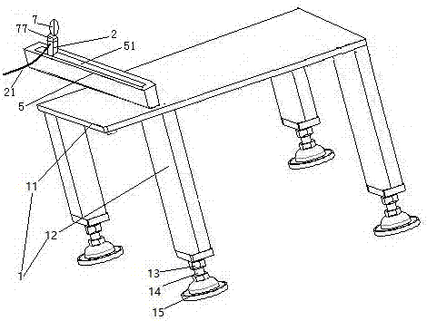
[0025] Embodiment one, see figure 1 , a frame of a lead sealing machine, including a frame 1 and an illuminating lamp 7 . The rack 1 includes a panel 11 and support feet 12 . A nut 13 is provided at the lower end of the supporting leg 12 . The nut 13 is threadedly connected with a screw rod 14 . The lower end of the screw rod 14 is provided with a supporting sole 15 . When in use, the length of the supporting legs is adjusted by turning the screw rod 14 to realize the level of the bar adjustment panel 11 .
[0026] The panel 11 is provided with a slide rail 5 with a slide groove 51 . The lamp holder 2 is slidably connected in the slide groove 51 . The lamp socket 2 is provided with a power lead-in wire 21 .
[0027] The lamp cap 77 of the illuminating lamp 7 is connected on the base 2 .
[0028] When in use, slide the base 2 to change the position of the illuminating lamp 7 . Power is introduced through the power lead-in wire 21 to supply the lighting lamp 7 .
Embodiment 2
[0029] Embodiment two, the difference with embodiment one is:
[0030] The base is also provided with a grease nipple for lubricating the chute 51 .
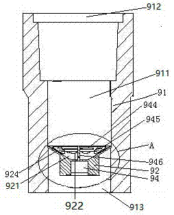
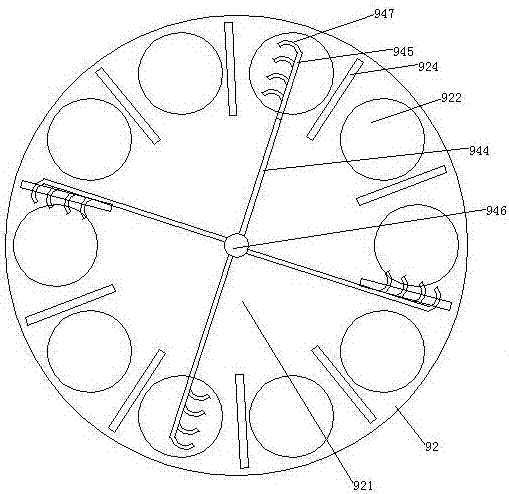
[0031] see figure 2, The filler nozzle 9 includes a filler nozzle body 91 and a filter plate 92 . The fuel nozzle body 91 is a cylindrical structure extending in the vertical direction. A flow channel 911 is provided in the fuel nozzle body 91 . The flow channel 911 penetrates along the nozzle body 91 from the upper end surface to the lower end surface of the nozzle body 91 . The inlet end 912 of the flow channel is located on the upper surface of the nozzle body 91 , and the outlet end 913 of the flow channel is located on the lower surface of the nozzle body 91 . The filter plate 92 is disposed in the flow channel 911 . The filter plate 92 is fixedly connected with the flow channel 911 . The end of the filter plate 92 facing the inlet end, that is, the upper end in the figure, is provided with a conical recess 921 . A ...
Embodiment 3
[0042] Embodiment three, the difference with embodiment two is:
[0043] see Figure 6 , The lamp cup has two sections, specifically a connecting section 721 and a cylindrical section 722 . Both the connecting section 721 and the cylindrical section 722 are wrapped with a thermally conductive film layer 78 . One end of the connecting section 721 is connected with the lamp cap. The cylindrical section 722 is rotatably connected to the connecting section 721 . The cooling plate 71 includes two cooling fins 713 . An airflow channel 714 is formed between the two cooling fins 713 . The air flow channel 714 is disconnected from the cavity 724 . The circuit boards 741 of the two LED light sources 74 are mounted on the two heat sinks 713 in a one-to-one correspondence.
[0044] see Figure 7 , the connecting section 721 is provided with a plurality of chucks 725 axially distributed along the cylindrical section 722 . The cylindrical section 722 is provided with an annular lock...
PUM
 Abstract
Description
Claims
Application Information
 - R&D
- Intellectual Property
- Life Sciences
- Materials
- Tech Scout
- Unparalleled Data Quality
- Higher Quality Content
- 60% Fewer Hallucinations
Browse by: Latest US Patents, China's latest patents, Technical Efficacy Thesaurus, Application Domain, Technology Topic, Popular Technical Reports.
© 2025 PatSnap. All rights reserved.Legal|Privacy policy|Modern Slavery Act Transparency Statement|Sitemap|About US| Contact US: help@patsnap.com