Electronic component waste crushing treatment equipment

A technology for electronic components and processing equipment, which is applied in the field of electronic component waste crushing and processing equipment, and can solve the problems of debris damage, poor effect, and slow crushing speed, etc.

Inactive Publication Date: 2017-07-18
冯晓栋
View PDF0 Cites 22 Cited by
  • Summary
  • Abstract
  • Description
  • Claims
  • Application Information

AI Technical Summary

Problems solved by technology

[0005] In order to overcome the shortcomings of slow crushing speed, poor effect, and easy damage by debris ejected from electronic components when manually crushing electronic component waste, the technical problem to be solved by the present invention is To provide a crushing and processing equipment for electronic component waste with good crushing effect and fast crushing speed, which will not be damaged by debris ejected from electronic components

Method used


Image

  • Electronic component waste crushing treatment equipment
  • Electronic component waste crushing treatment equipment
  • Electronic component waste crushing treatment equipment

Examples


Embodiment 1

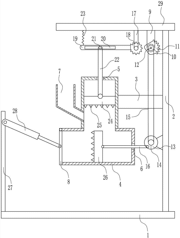
[0036] A crushing and processing equipment for electronic component waste, such as Figure 1-8 As shown, it includes a bottom plate 1, a right side plate 2, a fixed block 3, a processing box 4, a lower hopper 7, a first baffle plate 8, a first vertical rod 9, a first motor 10, a sector gear 11, a driven wheel 12, Turntable 13, driving wheel 14, the first backguy 15, the first push rod 16, the second vertical bar 17, the first gear 18, cross plate 19, roller 21, the second push rod 22, the first spring 23, the first The crushing plate 24, the crushing teeth 25, the second crushing plate 26, the left plate 27 and the first cylinder 28, the right side plate 2 is installed on the top right side of the bottom plate 1 through bolt connection, and the middle part of the left side of the right plate 2 passes through The mode of bolt connection is equipped with fixed block 3, and the left end of fixed block 3 is installed with processing box 4 by the mode of bolt connection, has the fi...

Embodiment 2

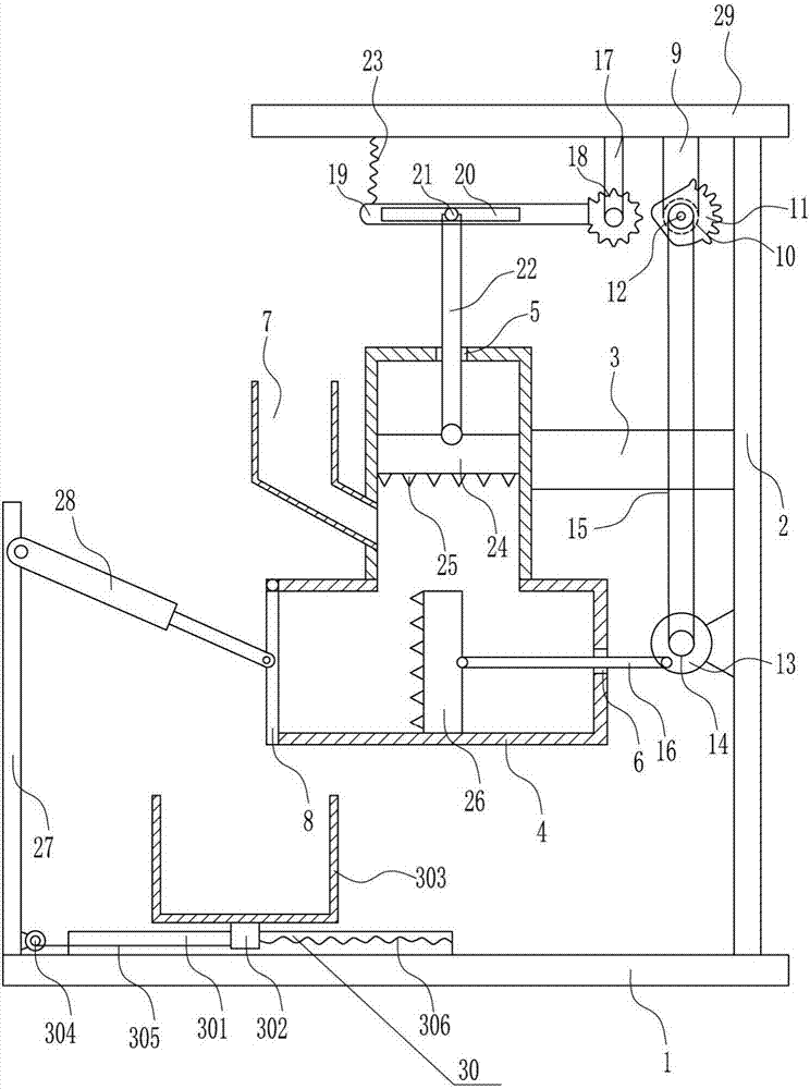
[0038] A crushing and processing equipment for electronic component waste, such as Figure 1-8 As shown, it includes a bottom plate 1, a right side plate 2, a fixed block 3, a processing box 4, a lower hopper 7, a first baffle plate 8, a first vertical rod 9, a first motor 10, a sector gear 11, a driven wheel 12, Turntable 13, driving wheel 14, the first backguy 15, the first push rod 16, the second vertical bar 17, the first gear 18, cross plate 19, roller 21, the second push rod 22, the first spring 23, the first The crushing plate 24, the crushing teeth 25, the second crushing plate 26, the left plate 27 and the first cylinder 28, the right side plate 2 is installed on the top right side of the bottom plate 1 through bolt connection, and the middle part of the left side of the right plate 2 passes through The mode of bolt connection is equipped with fixed block 3, and the left end of fixed block 3 is installed with processing box 4 by the mode of bolt connection, has the fi...

Embodiment 3

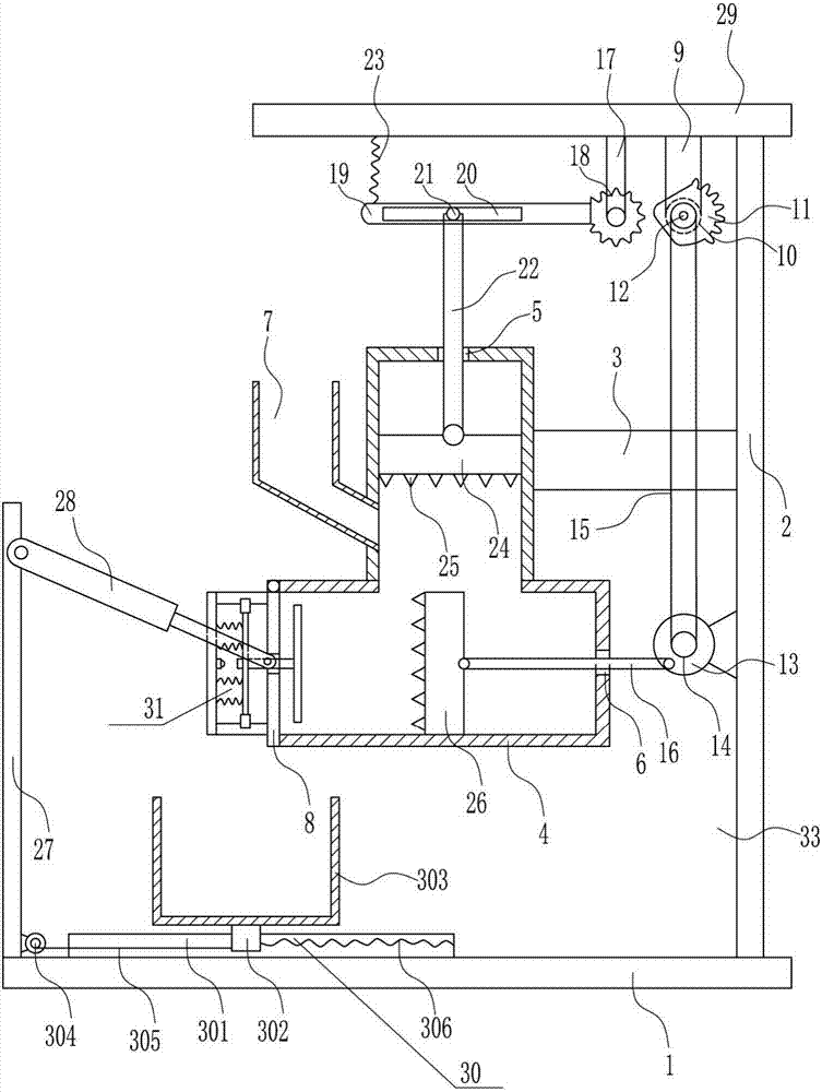
[0041] A crushing and processing equipment for electronic component waste, such as Figure 1-8As shown, it includes a bottom plate 1, a right side plate 2, a fixed block 3, a processing box 4, a lower hopper 7, a first baffle plate 8, a first vertical rod 9, a first motor 10, a sector gear 11, a driven wheel 12, Turntable 13, driving wheel 14, the first backguy 15, the first push rod 16, the second vertical bar 17, the first gear 18, cross plate 19, roller 21, the second push rod 22, the first spring 23, the first The crushing plate 24, the crushing teeth 25, the second crushing plate 26, the left plate 27 and the first cylinder 28, the right side plate 2 is installed on the top right side of the bottom plate 1 through bolt connection, and the middle part of the left side of the right plate 2 passes through The mode of bolt connection is equipped with fixed block 3, and the left end of fixed block 3 is installed with processing box 4 by the mode of bolt connection, has the fir...


PUM


Abstract

The invention relates to a crushing and processing equipment, in particular to a crushing and processing equipment for electronic component wastes. The technical problem to be solved by the present invention is to provide an electronic component waste crushing and processing equipment with good crushing effect, fast crushing speed, and no damage to the debris ejected from the electronic components. In order to solve the above technical problems, the present invention provides such an electronic component waste crushing and processing equipment, including a bottom plate, a right side plate, a fixed block, a processing box, a lower hopper, a first baffle, a first vertical rod, a first A motor, sector gear, driven wheel, turntable, driving wheel, etc.; the right side plate is installed on the right side of the top of the bottom plate by means of bolts, and the middle of the left side of the right side plate is installed with a fixed block by means of bolt connection. In the present invention, the waste of electronic components is crushed up and down by the first crushing plate, and the waste of electronic components is crushed from left to right by the second crushing plate, thereby accelerating the crushing speed.

Description

technical field [0001] The invention relates to crushing treatment equipment, in particular to a crushing treatment equipment for electronic component waste. Background technique [0002] Electronic components are components of electronic components and small electrical machines and instruments. They are often composed of several parts and can be used in similar products; they often refer to certain parts in industries such as electrical appliances, radios, and instruments, such as capacitors and transistors. The general term for sub-devices such as springs, hairsprings, and springs. Common ones include diodes, etc. Electronic components include: resistors, capacitors, potentiometers, electron tubes, radiators, electromechanical components, connectors, semiconductor discrete devices, electroacoustic devices, laser devices, electronic display devices, optoelectronic devices, sensors, power supplies, switches, micro-motors , electronic transformers, relays, printed circuit b...

Claims


Application Information

Patent Timeline
Patent Type & Authority Applications(China)
IPC IPC(8): B02C1/00B02C1/14B02C23/00
CPCB02C1/00B02C1/14B02C23/00B02C2201/06
Inventor 冯晓栋
Owner 冯晓栋
Why Eureka
Try Eureka