Stamping die achieving side-edge positioning

A stamping die and positioning rod technology, which is applied in the field of stamping dies, can solve the problems of no positioning scale, slow positioning speed, and affecting molding quality, so as to achieve the effect of flexible use and avoiding disordered positions

Active Publication Date: 2017-07-18
滁州市东华模具制造有限公司
View PDF9 Cites 14 Cited by
  • Summary
  • Abstract
  • Description
  • Claims
  • Application Information

AI Technical Summary

Problems solved by technology

[0003] However, when the existing stamping die continuously stamps the material plate to be stamped, since the existing stamping die does not have a structure for positioning and restricting the material plate to be stamped, it is easy to be formed when the material plate to be stamped is continuously stamped by the stamping die. Punching route deviates, affecting molding quality
At the same time, the existing stamping dies do not have a positioning scale, and there is no reference information when positioning the parts, the positioning speed is slow, and the use is not flexible enough

Method used


Image

  • Stamping die achieving side-edge positioning
  • Stamping die achieving side-edge positioning
  • Stamping die achieving side-edge positioning

Examples


Embodiment Construction

[0018] The following will clearly and completely describe the technical solutions in the embodiments of the present invention with reference to the accompanying drawings in the embodiments of the present invention. Obviously, the described embodiments are only some, not all, embodiments of the present invention.

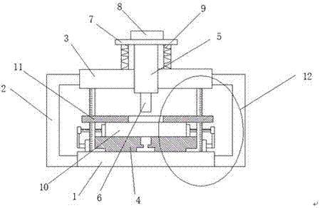
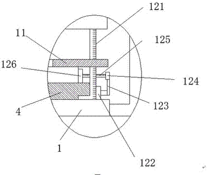
[0019] refer to Figure 1-4 , a side-positioned stamping die, including a base 1, a support rod 2 is fixed on both sides of the base 1, and a guide plate 3 is fixed on the top of the support rod 2, and the top of the guide plate 3 is provided with a mounting plate through the guide plate 3 hole, and a guide block 5 is slidably installed in the mounting hole, the top of the guide block 5 is fixed with a limit plate 7, and the bottom of the guide block 5 is fixed with an upper punch 6, and the top of the limit plate 7 is fixed with a connecting block 8, and Both sides of the limiting plate 7 are provided with a spring 9, one end of the spring 9 is fixedly connected wit...


PUM


Abstract

The invention discloses a stamping die achieving side-edge positioning. The stamping die comprises a base, supporting rods are fixed to the two sides of the base, a guiding plate is fixed to the tops of the supporting rods, an installing hole which penetrates through the guiding plate is formed in the top of the guiding plate, and a guiding block is installed in the installing hole in a sliding manner; a limiting plate is fixed to the top of the guiding block, an upper male die is fixed to the bottom of the guiding block, a connecting block is fixed to the top of the limiting plate, and the two sides of the limiting plate are each provided with a spring; and one end of each spring is fixedly connected with the guiding plate, the other end of each spring is fixedly connected with the limiting plate, and a lower male die is fixed to the upper portion of the top of the base. According to the stamping die achieving side-edge positioning, by means of matching usage of structures such as push-rod motors, connecting rods and fixing plates, clamping blocks can be positioned, a to-be-stamped material plate can be limited, when the to-be-stamped material plate is subjected to continuous stamping, locations which need to be stamped are located in a straight line, and therefore the situation that the quality is affected due to dislocation of stamping formed holes in the stamped material plate is avoided.

Description

technical field [0001] The invention relates to the technical field of stamping dies, in particular to a stamping die with side positioning. Background technique [0002] Stamping die is a special process equipment for processing materials (metal or non-metal) into parts (or semi-finished products) in cold stamping processing, called cold stamping die (commonly known as cold stamping die). Stamping is a pressure processing method that uses a mold installed on a press to apply pressure to the material at room temperature to cause separation or plastic deformation to obtain the required parts. At present, the punching mold generally consists of a punch and It can be composed of one die, or it can be composed of multiple punches and multiple dies. [0003] However, when the existing stamping die continuously stamps the material plate to be stamped, since the existing stamping die does not have a structure for positioning and restricting the material plate to be stamped, it is ...

Claims


Application Information

Patent Timeline
Patent Type & Authority Applications(China)
IPC IPC(8): B21D37/10B21D37/12B21D43/00
CPCB21D37/10B21D37/12B21D43/003
Inventor 王华东蒋业华乔龙功
Owner 滁州市东华模具制造有限公司
Why Eureka
Try Eureka