Semiconductor defrosting heater and refrigeration equipment

A frost heater and semiconductor technology, applied in the field of semiconductor defrosting heaters and a refrigeration equipment, can solve the problems of temperature rise, low heat utilization rate of heating pipes, affecting user experience, etc., and achieve the improvement of energy utilization rate. Effect

Inactive Publication Date: 2017-07-18
HEFEI MIDEA REFRIGERATOR CO LTD +2
View PDF2 Cites 9 Cited by
  • Summary
  • Abstract
  • Description
  • Claims
  • Application Information

AI Technical Summary

Problems solved by technology

[0003] (1) When the defrosting heating tube 102 heats and defrosts, the temperature inside the refrigerator and other refrigeration equipment will also rise accordingly, which affects the user experience;
[0004] (2) The defrosting heating pipe 102 is installed at the bottom of the evaporator 104, and the heat of the defrosting heating pipe 102 radiates to the surroundings, resulting in a low heat utilization rate of the heating pipe;
[0005] (3) The heating wires and flame-retardant materials installed in the defrosting heating tube 102 need to be connected to strong electricity, which also has potential safety hazards while realizing automatic defrosting

Method used


Image

  • Semiconductor defrosting heater and refrigeration equipment
  • Semiconductor defrosting heater and refrigeration equipment
  • Semiconductor defrosting heater and refrigeration equipment

Examples


Embodiment 1

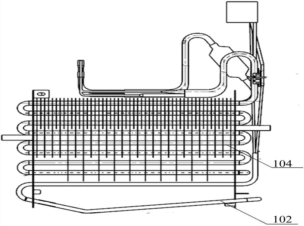
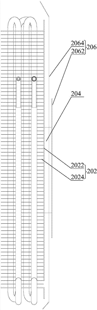
[0050] like figure 2 and Figure 4 As shown, in any of the above embodiments, preferably, the heat dissipation part 202 includes: a heat dissipation plate 2022, arranged side by side with the evaporator, and connected to the semiconductor cooling assembly 204; a plurality of heat dissipation fins 2024, along the air outlet direction of the evaporator One end of the cooling fin 2024 is connected to the cooling plate 2022, and the other end of the cooling fin 2024 is extended to be in contact with the evaporator.

[0051] In this embodiment, by contacting the heat dissipation plate 2022 with the semiconductor refrigeration assembly 204, the heat conduction efficiency of the semiconductor refrigeration assembly 204 to the outside is improved, and the heat dissipation area of ​​the semiconductor refrigeration assembly 204 is increased. 2024, a plurality of cooling fins 2024 are in contact with the evaporator, and transfer the heat on the cooling plate 2022 to the evaporator thro...

Embodiment 2

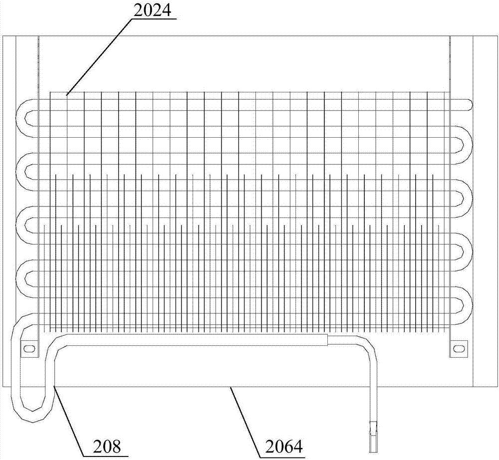
[0056] like image 3 As shown, in any of the above embodiments, preferably, the cooling fin 2024 is provided with a plurality of through holes in a direction perpendicular to the cooling plate 2022, and the cooling fin 2024 can be sleeved on the evaporator through the plurality of through holes.

[0057] In this embodiment, the radiating fins 2024 are evaporator fins on the evaporator. By providing a plurality of through holes on the radiating fins 2024, the evaporating tubes 208 of the evaporator can be distributed in various ways on the plurality of radiating fins 2024. Ways, for example, the evaporating tubes 208 can be distributed in multiple rows and columns on multiple cooling fins 2024 to improve space utilization and heat utilization of the cooling fins 2024 .

[0058] Preferably, the heat sink 2024 is sleeved on the evaporator through a plurality of through holes, periodically heating and defrosting the evaporator, and usually used as an evaporating fin of the evapora...


PUM


Abstract

The invention provides a semiconductor defrosting heater and refrigeration equipment, wherein the semiconductor defrosting heater comprises a heat dissipation part, a semiconductor refrigeration assembly and a refrigeration part, wherein the heat dissipation part, the semiconductor refrigeration assembly and the refrigeration part are sequentially arranged far away from an evaporator, and the semiconductor refrigeration assembly is connected with the heat dissipation part and the refrigeration part respectively through insulation heat conductors. By means of the technical scheme, on one hand, the effect of defrosting the evaporator is achieved, and compared with an existing defrosting heating pipe, the defrosting efficiency is improved, and electric energy is saved; on the other hand, the direct current needed by the semiconductor refrigeration assembly is under safe voltage, security and reliability are high, and potential safety hazards existing in the defrosting process of the defrosting heating pipe are reduced.

Description

technical field [0001] The invention relates to the technical field of refrigeration equipment, in particular to a semiconductor defrosting heater and a refrigeration equipment. Background technique [0002] related technologies, such as figure 1 As shown, the defrosting heater uses the defrosting heating tube 102 to periodically heat and defrost the evaporator 104. Although the defrosting heating tube 102 solves the problem of manual defrosting, in the actual defrosting heating process, the defrosting heating Tube 102 still has the following drawbacks: [0003] (1) When the defrosting heating tube 102 heats and defrosts, the temperature inside the refrigerator and other refrigeration equipment will also rise accordingly, which affects the user experience; [0004] (2) The defrosting heating pipe 102 is installed at the bottom of the evaporator 104, and the heat of the defrosting heating pipe 102 radiates to the surroundings, resulting in a low heat utilization rate of the...

Claims


Application Information

Patent Timeline
Patent Type & Authority Applications(China)
IPC IPC(8): F25B21/02F25B47/02
CPCF25B21/02F25B47/02
Inventor 宋亚雷唐学强任伟何静
Owner HEFEI MIDEA REFRIGERATOR CO LTD
Why Eureka
Try Eureka