Implantable light splitting machine

A spectrometer and implantable technology, applied in sorting and other directions, can solve the problems of unstable operation of implantable spectrometers, and achieve the effects of reducing body size, fast feeding, and improving stability

Active Publication Date: 2017-07-21
深圳市朝阳光科技有限公司
View PDF11 Cites 0 Cited by
  • Summary
  • Abstract
  • Description
  • Claims
  • Application Information

AI Technical Summary

Problems solved by technology

[0003] The present invention provides an implantable spectrometer to solve the problem that the feeding path and adsorption path of the LED components in the existing implantable spectrometer are not connected, which makes the operation of the implantable spectrometer unstable.

Method used


Image

  • Implantable light splitting machine
  • Implantable light splitting machine
  • Implantable light splitting machine

Examples


Embodiment Construction

[0027] In order to make the object, technical solution and advantages of the present invention clearer, the implementation manner of the present invention will be further described in detail below in conjunction with the accompanying drawings.

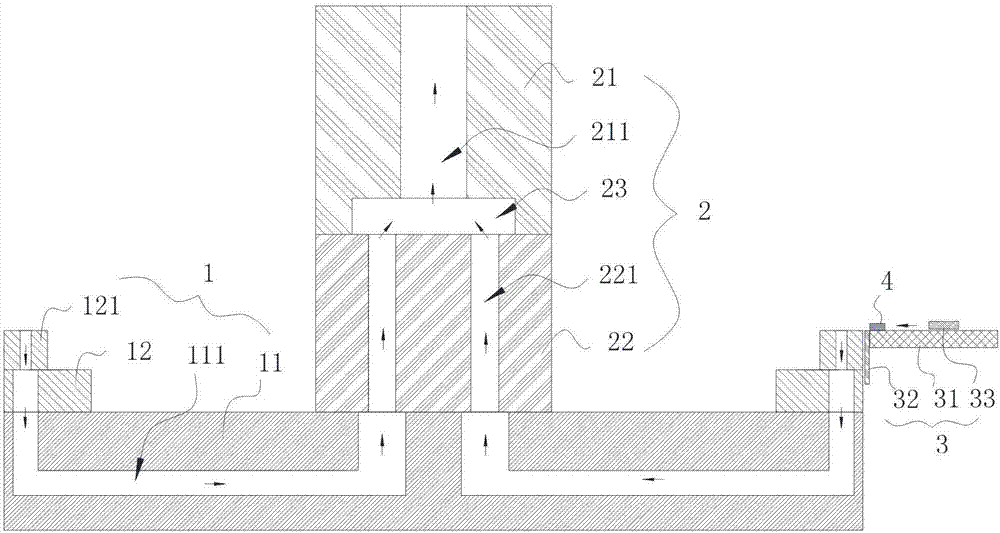
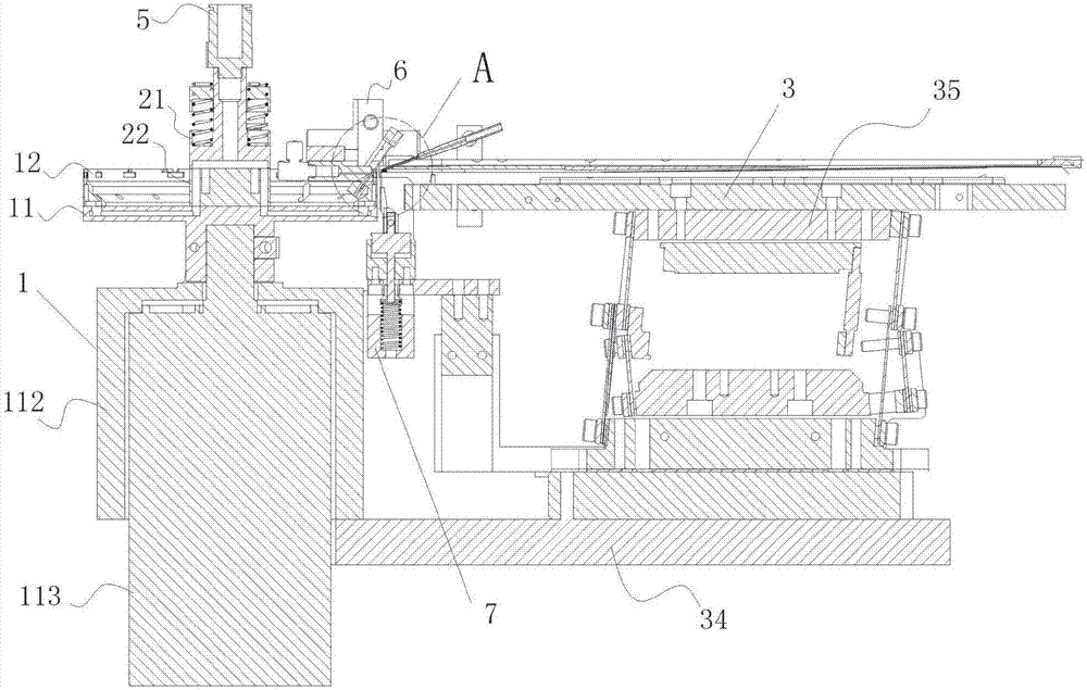
[0028] The implantable spectrometer provided by the present invention includes a mounting frame on which an indexing plate assembly, a manifold assembly and a feeding assembly are arranged.

[0029] Among them, the index plate assembly includes the index plate and the suction nozzle seat arranged on the index plate. The index plate includes a plurality of relatively independent first air passages, and the first air passages include a first end air port and a second air port. The air port at the end; the nozzle seat includes a nozzle corresponding to the air port at the first end, and the nozzle communicates with the air port at the first end.

[0030] The manifold assembly includes a first manifold and a second manifold, the first mani...


PUM


Abstract

The invention discloses an implantable light splitting machine. The implantable light splitting machine comprises a mounting frame, and the mounting frame comprises an index plate assembly, a confluence plate assembly and a feeding assembly. The index plate assembly comprises an index plate and a suction nozzle seat arranged on the index plate, and the index plate comprises a first air flue. The confluence plate assembly comprises a first confluence plate and a second confluence plate, the first confluence plate comprises a second air flue, the second confluence plate comprises a third air flue, and an airtight air chamber is formed between the first confluence plate and the second confluence plate. The first air flue, the third air flue, the airtight chamber and the second air flue sequentially communicate with one another. The feeding assembly is located on one side of the index plate assembly and comprises a flow rail, an obstructing piece and an air blowing piece. The output end of the flow rail is arranged on the position close to the suction nozzle, the obstructing piece and the air blowing piece are both arranged at the output end of the flow rail, and the blowing pathway of the air blowing piece intersects with the adsorbing pathway of the suction nozzle.

Description

technical field [0001] The invention relates to an implantable optical splitter. Background technique [0002] LED (Light Emitting Diode, Light Emitting Diode) components need to undergo color separation and light separation treatment before packaging and leaving the factory. LEDs are sorted according to different parameters (electricity, brightness, color, etc.). A kind of equipment for sorting, including indexing plate assembly and pick-and-place mechanism. In the existing implantable spectrometer, the index plate assembly includes an index plate with a plurality of suction nozzles, and the LED components are adsorbed and fixed by forming a negative pressure at the suction nozzles, but the existing structure causes the gap between each suction nozzle There is a problem of uneven adsorption force, which makes the test unstable. At the same time, the pick-and-place mechanism of the existing implantable spectrometer mostly picks up the LED components from the front end of t...

Claims


Application Information

Patent Timeline
Patent Type & Authority Applications(China)
IPC IPC(8): B07C5/02B07C5/344B07C5/342
CPCB07C5/02B07C5/342B07C5/344
Inventor 邓朝旭
Owner 深圳市朝阳光科技有限公司
Why Eureka
Try Eureka