Side locking device for lifting appliance on electrophoresis conveying line

A conveying line and spreader technology, applied in electrophoretic plating, electrolytic coatings, coatings, etc., to avoid insufficient space and prevent accumulation

Active Publication Date: 2017-07-21
大唐互联科技(武汉)有限公司
View PDF11 Cites 0 Cited by
  • Summary
  • Abstract
  • Description
  • Claims
  • Application Information

AI Technical Summary

Problems solved by technology

[0003] In view of the fact that non-load-bearing body structures such as miniature vehicles, commercial vehicles, and light trucks generally have rear suspension beam mounting lugs and pipe beams, the present invention provides a multi-vehicle universal The unique locking device solves the problem of collinear production of non-load-bearing body pre-treatment electrophoresis

Method used


Image

  • Side locking device for lifting appliance on electrophoresis conveying line
  • Side locking device for lifting appliance on electrophoresis conveying line
  • Side locking device for lifting appliance on electrophoresis conveying line

Examples


Embodiment Construction

[0022] In order to make the purpose, technical solutions and advantages of the present invention clearer, the present invention will be further described below in conjunction with the accompanying drawings and embodiments. It should be understood that the specific embodiments described here are only used to explain the present invention and are not intended to limit this invention.

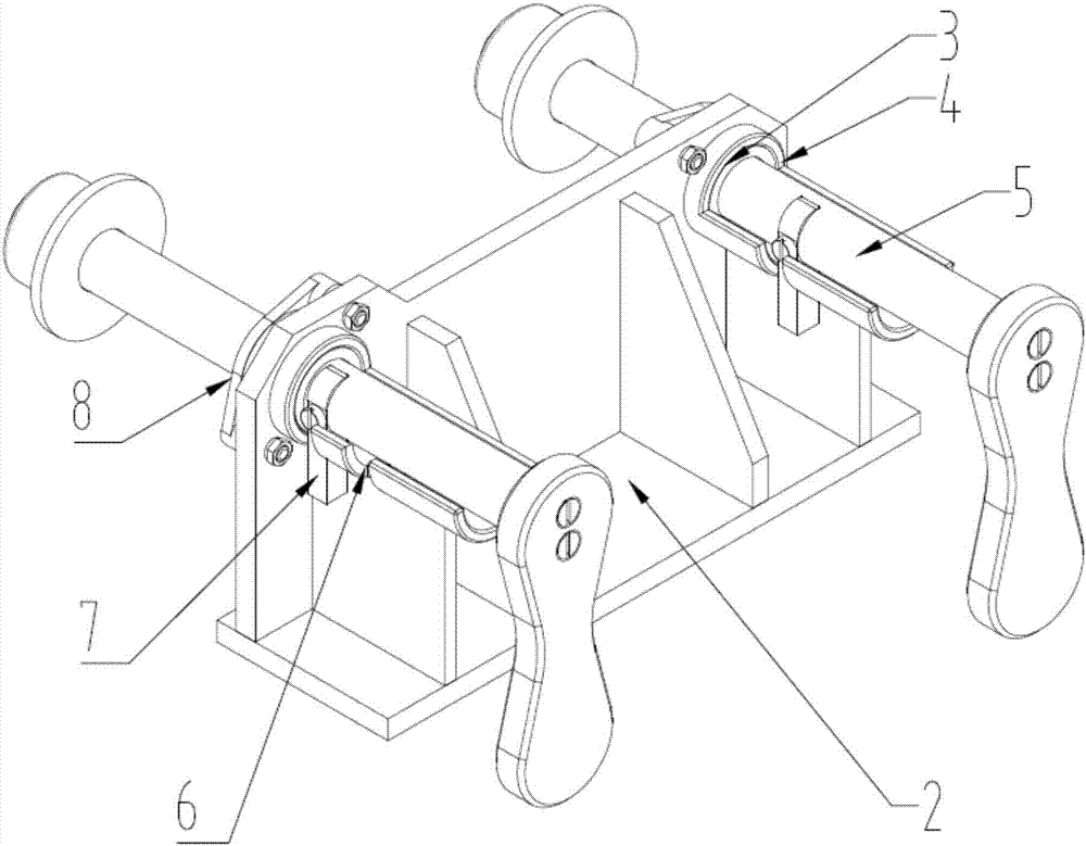
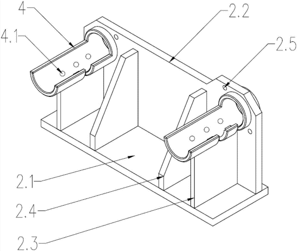
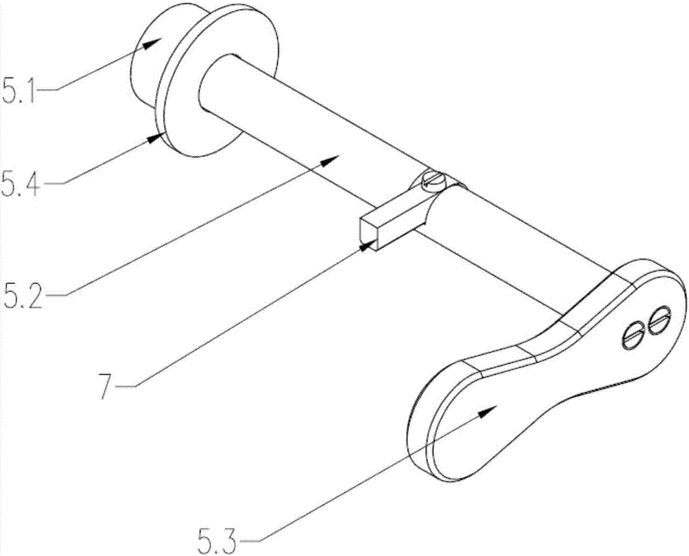
[0023] Such as figure 1 As shown, a side locking device for an electrophoresis transmission line sling includes a locking bracket 2, and mounting holes 3 are provided at both ends of the locking bracket 2, and a mounting seat 4 is provided through the mounting holes 3. One end of the mounting seat 4 is a casing structure, and the other end is a semi-open casing structure. The casing structure of the mounting seat 4 is arranged in the mounting hole 3, and a locking pin assembly 5 is also provided through the mounting seat 4. One side of the mounting base 4 is provided with a concave groove 6, and ...


PUM


Abstract

The invention relates to a side locking device for a lifting appliance on an electrophoresis conveying line. By adoption of the side locking device, a novel locking method is provided for a vehicle provided with front lifting lugs suspended on the rear portion. The whole locking device is mounted on two side beams of the lifting appliance through a locking support. The locking device specifically comprises the locking support. Mounting bases are arranged at the two ends of the locking support through mounting holes. One end of each mounting base is of a sleeve structure, and the other end of each mounting base is of a semi-open sleeve structure. The two ends of the locking support penetrate through the mounting bases and provided with locking pin assemblies. A concave clamping groove is formed in one side of each mounting base. Clamping tongues are arranged on the locking pin assemblies, clamped in the concave clamping grooves and tightly matched with the concave clamping grooves. By adoption of the locking device, a traditional locking way that only a bottom supporting beam is locked is eliminated, the locking device is more suitable for the current situation of micro-surfaces and mixed-line production of cars, the phenomenon that the traditional locking device is prone to being covered with paint is avoided fundamentally, and the use intensity is reliable.

Description

technical field [0001] The invention belongs to the field of pre-treatment electrophoresis technology for non-load-bearing car bodies such as mini-cars, commercial vehicles, and light trucks, and relates to a side locking device, in particular to a side locking device on a pre-treatment electrophoresis transmission line spreader. Background technique [0002] At present, most domestic manufacturers of non-load-bearing bodies such as mini-cars, commercial vehicles, and light trucks have mixed-line production of multiple models. The device is in the form of a front-end positioning pin and a rear-end locking hook, but this device cannot adapt to the mixed production of multiple models. In the pre-treatment electrophoresis, it is often necessary to replace the locking device according to the model, which brings inconvenience to production. Therefore, it is particularly important to design a locking device that can adapt to multi-vehicle pre-treatment electrophoresis spreaders. ...

Claims


Application Information

Patent Timeline
Patent Type & Authority Applications(China)
IPC IPC(8): C25D13/22
CPCC25D13/22
Inventor 鲍雁锟徐军胡锦明詹开洪李军何宁波章书乐
Owner 大唐互联科技(武汉)有限公司
Why Eureka
Try Eureka