Rotating joint with hydraulic self-locking function

A rotary joint and self-locking technology, which is applied in the direction of fluid pressure actuation device, etc., can solve the problems of high cost, complex structure of oil cylinder, low safety and reliability, and achieve the effect of saving electric energy

Active Publication Date: 2017-07-21
无锡市艾可密封技术有限公司
View PDF6 Cites 0 Cited by
  • Summary
  • Abstract
  • Description
  • Claims
  • Application Information

AI Technical Summary

Problems solved by technology

[0003] However, the existing rotary hydraulic cylinders with self-locking function are all realized by adding more accessories, which will inevitably lead to complex structure, high cost, and low safety and reliability of the cylinder.

Method used


Image

  • Rotating joint with hydraulic self-locking function
  • Rotating joint with hydraulic self-locking function

Examples


Embodiment 1

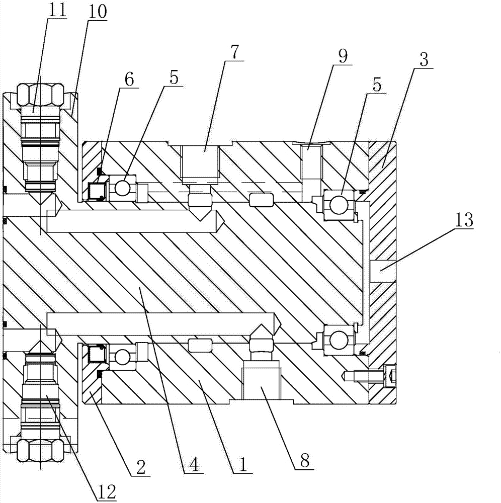
[0017] see figure 1 as shown, figure 1 It is a schematic structural diagram of a rotary joint with hydraulic self-locking function provided in Embodiment 1 of the present invention.

[0018] In this embodiment, a rotary joint with a hydraulic self-locking function includes a housing 1, an end cover 2, a tail cover 3 and a rotating shaft 4, and the two ends of the housing 1 are respectively installed with the end cover 2 and the tail cover 3, so that The rotating shaft 4 is rotatably arranged in the housing 1 , and bearings 5 ​​are provided between both ends and the housing 1 , and rotating lip seals 6 are provided between the end cover 2 and the rotating shaft 4 .

[0019] The housing 1 is provided with a first oil port 7, a second oil port 8 and an oil drain port 9, the outer end of the rotating shaft 4 is provided with a mounting flange 10, and the mounting flange 10 is provided with a second A hydraulically controlled one-way valve 11 and a second hydraulically controlled...

Embodiment 2

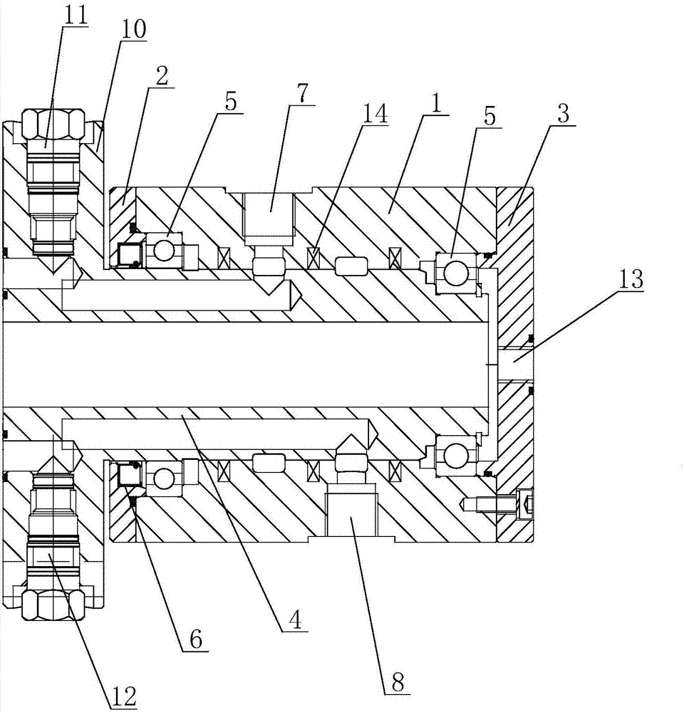
[0023] see figure 2 as shown, figure 2 It is a schematic structural diagram of a rotary joint with hydraulic self-locking function provided by Embodiment 2 of the present invention.

[0024] The main difference between this embodiment and Embodiment 1 is that the sealing form between the rotating shaft 4 and the housing 1 is different. In this embodiment, several high-pressure channels are arranged between the rotating shaft 4 and the housing 1. sealing ring 14. The sealing of the hydraulic oil is realized by the high-pressure sealing ring 14 . At the same time, only the first oil port 7 and the second oil port 8 are opened on the housing 1 .


PUM


Abstract

The invention discloses a rotating joint with a hydraulic self-locking function. The rotating joint comprises a shell, an end cover, a tail cover and a rotation shaft; the end cover and the tail cover are installed at the two ends of the shell respectively, the rotation shaft is rotatably arranged in the shell, bearings are arranged between the rotation shaft and the shell, and the shell is provided with a first oil inlet and a second oil inlet; an installing flange is arranged at the outer end of the rotation shaft and provided with a first hydraulic control one-way valve and a second hydraulic control one-way valve, and the first hydraulic control one-way valve and the second hydraulic control one-way valve communicate with the first oil inlet and the second oil inlet through oil channels respectively to form a hydraulic lock. The rotating joint is arranged on a corresponding rotating hydraulic oil cylinder or other hydraulic components in a matched mode, and then oil can be continuously supplied when the hydraulic oil cylinder rotates; meanwhile, the oil cylinder can not move when the oil cylinder stops at any position, the position of an oil cylinder piston rod can be mastered in real time, the safety and the reliability are high, and a significant energy saving effect is achieved.

Description

technical field [0001] The invention relates to a rotary joint, in particular to a rotary joint with hydraulic self-locking function. Background technique [0002] Rotary joints are common components used in conjunction with hydraulic cylinders or other hydraulic components. At present, the existing rotary hydraulic oil cylinder or other hydraulic components may lose pressure due to failure of the hydraulic station, resulting in safety accidents. Therefore, most rotary hydraulic cylinders are equipped with a self-locking function. [0003] However, the existing rotary hydraulic oil cylinders with self-locking function are all realized by adding more accessories, which will inevitably lead to complex structure, high cost, and low safety and reliability of the oil cylinder. Contents of the invention [0004] The object of the present invention is to provide a rotary joint with hydraulic self-locking function, which has the characteristics of simple structure, low cost and ...

Claims


Application Information

Patent Timeline
Patent Type & Authority Applications(China)
IPC IPC(8): F15B15/20F15B15/26
CPCF15B15/20F15B15/26F15B2015/268
Inventor 倪冬梅张志娟
Owner 无锡市艾可密封技术有限公司
Why Eureka
Try Eureka