
Electrical engineering control cabinet

A technology of electrical engineering and control cabinets, applied in the electrical field, can solve the problems of inconvenient dehumidification, scattered lines, poor storage function, etc., and achieve the effect of improving the function of carding lines, preventing scattered lines, and improving storage functions

Active Publication Date: 2017-07-21
XIANGTAN UNIV
View PDF3 Cites 6 Cited by
  • Summary
  • Abstract
  • Description
  • Claims
  • Application Information

AI Technical Summary

Problems solved by technology

However, when the electrical control cabinet is in use, it is well known that various components in the circuit will generally generate heat after working for a long time, and inside the electrical control cabinet, a large number of circuit components will be densely arranged on a cabinet wall , This will lead to more serious heat production inside the electrical control cabinet, and circuit accidents are prone to occur. Therefore, it is necessary to solve the heat production problem of the electrical control cabinet. At the same time, it is inconvenient to dehumidify, not energy-saving and environmentally friendly, and prone to scattered lines. The overall storage function is poor, and it is inconvenient to maintain under low light conditions

Method used


Image

  • Electrical engineering control cabinet
  • Electrical engineering control cabinet
  • Electrical engineering control cabinet

Examples


Embodiment Construction

[0021] The following will clearly and completely describe the technical solutions in the embodiments of the present invention with reference to the accompanying drawings in the embodiments of the present invention. Obviously, the described embodiments are only some, not all, embodiments of the present invention. Based on the embodiments of the present invention, all other embodiments obtained by persons of ordinary skill in the art without making creative efforts belong to the protection scope of the present invention.

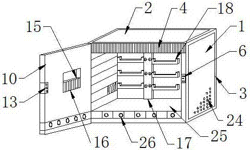
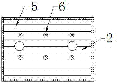
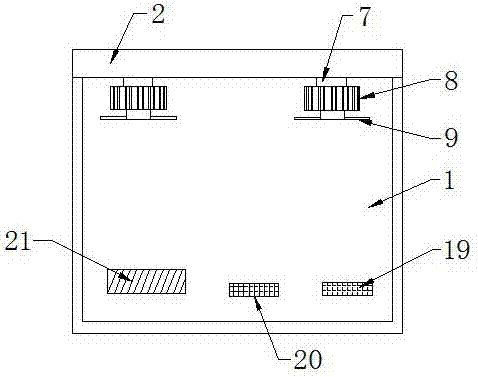
[0022] see Figure 1-6 , the present invention provides an electrical engineering control cabinet: comprising an electrical engineering control cabinet body 1, a top cover 2 is arranged on the top of the electrical engineering control cabinet body 1, a conductive fiber 3 is arranged on the outside of the electrical engineering control cabinet body 1, and a top cover 2 One side of the top cover 2 is provided with a protective cover 4, the inner side of the top ...


PUM


Abstract

The invention discloses an electrical engineering control cabinet. The control cabinet comprises an electrical engineering control cabinet body. A top cover is arranged on the top end of the electrical engineering control cabinet body. A conductive fiber is arranged on the outer side of the electrical engineering control cabinet body. A protection sleeve is arranged on one side of the top cover. A heat dissipation strip is arranged on the inner side of the top cover. An illumination lamp is arranged on one side of the heat dissipation strip. A connection rod is arranged on one side of the illumination lamp. A heat dissipation fan is arranged on the bottom end of the connection rod. Heat dissipation fan blades are arranged on the bottom end of the heat dissipation fan. According to the invention, specific temperature and humidity in an electrical engineering control cabinet can be easily known; heat dissipation or dehumidification can be easily performed on the interior of the electrical engineering control cabinet in an intelligent and convenient manner; certain quantity of heat energy can be easily converted into electric energy and stored in a storage battery, so energy is saved and environment is protected; the whole wire arrangement function is easily improved; the phenomenon of messy circuits is avoided; improvement of the whole object storage function is facilitated; improvement of brightness in the control cabinet is facilitated under the condition of quite dark light; and the cabinet is easy to repair.

Description

technical field [0001] The invention relates to the electrical field, in particular to an electrical engineering control cabinet. Background technique [0002] The electrical control cabinet is a cabinet made of steel to protect the normal operation of circuit components. The materials for making electrical control cabinets are generally divided into two types: hot-rolled steel and cold-rolled steel. Electrical control cabinets are widely used mainly in chemical industry, environmental protection industry, power system, metallurgical system, industry, nuclear power industry, fire safety monitoring, transportation industry and so on. However, when the electrical control cabinet is in use, it is well known that various components in the circuit will generally generate heat after working for a long time, and inside the electrical control cabinet, a large number of circuit components will be densely arranged on a cabinet wall , This will lead to more serious heat production in...

Claims


Application Information

Patent Timeline
IPC IPC(8): H02B1/56H02B1/28H02B1/30H02J7/32
CPCH02B1/28H02B1/30H02B1/565H02J7/32
Inventor 罗培段政彤
Owner XIANGTAN UNIV
Learn More