Wire holder

A technology of wire clips and wires, which is applied in the field of electric power, can solve problems such as insufficient clamping, safety, and hidden dangers, and achieve the effect of convenient traction

Inactive Publication Date: 2017-07-21
浙江特意电气有限公司
View PDF3 Cites 0 Cited by
  • Summary
  • Abstract
  • Description
  • Claims
  • Application Information

AI Technical Summary

Problems solved by technology

[0002] In the process of electric power maintenance, it is often necessary to pull the wires. The electric power personnel usually directly clamp the outer insulation layer with their hands or use pliers to operate, which poses a safety hazard, and the wires are easy to slip and the clamping is not tight enough.

Method used


Image

  • Wire holder
  • Wire holder
  • Wire holder

Examples


Embodiment Construction

[0019] The following will clearly and completely describe the technical solutions in the embodiments of the present invention with reference to the accompanying drawings in the embodiments of the present invention. Obviously, the described embodiments are only some, not all, embodiments of the present invention. Based on the embodiments of the present invention, all other embodiments obtained by persons of ordinary skill in the art without making creative efforts belong to the protection scope of the present invention.

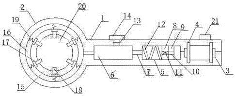
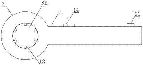
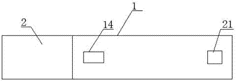
[0020] see figure 1 , figure 2 and image 3 , an embodiment provided by the present invention: a wire clamp, including a clamping rod 1 and a clamping part 2 integrated with the clamping rod 1, the inside of the clamping rod 1 is provided with a wire 4 of the iron rod 3, the first cavity 5 and the second cavity 6, the inside of the clamping rod 1 is provided with a through cavity 7 connecting the outside and the first cavity 5 and connecting the first cavit...


PUM


Abstract

The invention discloses a wire holder. The wire holder comprises a holding rod and a holding part integrated to the holding rod. An iron bar with a wire surrounding the exterior, a first cavity and a second cavity are arranged in the holding rod. A through cavity connecting the outside and the first cavity and a through cavity connecting the first cavity and the second cavity are arranged in the holding rod. A measurement and control device is arranged on the side face of the holding rod. A magnetic block is arranged on one end of the iron bar in the first cavity. An arm plate is fixed on one end face of the magnetic block. A first through cavity is arranged in the centers of the arm plate and the magnetic block. According to the invention, wires can be effectively clamped and easily dragged; in addition, electromagnetism is used for carrying out control, so the wire holder is controllable; and the wire holder controls the clamping degree of the wires according to the size of the current, so different requirements can be met.

Description

technical field [0001] The invention relates to the technical field of electric power, in particular to an electric wire holder. Background technique [0002] In the process of electric power maintenance, it is often necessary to pull the wires. The electric power personnel usually directly clamp the outer insulation layer with their hands or use pliers to operate, which poses a safety hazard, and the wires are easy to slip and the clamping is not tight enough. Contents of the invention [0003] The purpose of the present invention is to provide a wire clamp to solve the problems raised in the background art above. [0004] To achieve the above object, the present invention provides the following technical solutions: [0005] A wire clamper, comprising a clamping rod and a clamping part integrated with the clamping rod, the inside of the clamping rod is provided with an iron rod surrounded by wires, a first cavity and a second cavity, The inside of the clamping rod is pr...

Claims


Application Information

Patent Timeline
Patent Type & Authority Applications(China)
IPC IPC(8): H02G1/00
CPCH02G1/00
Inventor 叶梦佳
Owner 浙江特意电气有限公司
Why Eureka
Try Eureka