
Single-phase permanent magnet type switched reluctance motor and control method thereof

A switched reluctance motor and permanent magnet technology, applied in the direction of AC motor control, control system, magnetic circuit, etc., can solve the problems of inability to realize bidirectional operation, inability to generate continuous torque, large output torque fluctuations, etc., and achieve good performance Energy-saving effects, ease of modeling and simulation, and effects of increased power density

Active Publication Date: 2017-07-21
上海鼎特电器有限公司 +1
View PDF11 Cites 0 Cited by
  • Summary
  • Abstract
  • Description
  • Claims
  • Application Information

AI Technical Summary

Problems solved by technology

However, after the salient pole of the rotor is deformed, it is no longer the double salient pole structure in the original sense, so it will also lose or weaken the unique characteristics of the traditional double salient pole switched reluctance motor, and its control characteristics will also change, and this This kind of motor cannot realize bidirectional operation; in addition, the conventional single-phase switched reluctance motor has the disadvantages of large output torque fluctuation, low output torque density, and inability to produce continuous torque output.

Method used


Image

  • Single-phase permanent magnet type switched reluctance motor and control method thereof
  • Single-phase permanent magnet type switched reluctance motor and control method thereof
  • Single-phase permanent magnet type switched reluctance motor and control method thereof

Examples


Embodiment 1

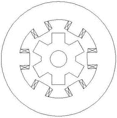
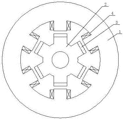
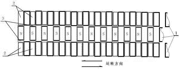
[0040] Embodiment 1: as figure 1 , 2As shown in and 3, a single-phase permanent magnet switched reluctance motor capable of bidirectional operation includes a stator 1, a rotor 2, a motor output shaft and a control system, and an air gap is formed between the salient poles of the stator 1 and the rotor 2 , the stator adopts a three-stage radial magnetic field design, the rotor core adopts a single-stage salient pole core structure, the corresponding relationship between the stator 1 and the rotor 2 is an inner rotor structure or an outer rotor structure, and the control system A polarity detection circuit, a position detection circuit and an energy recovery circuit are installed in the motor to meet the needs of motor start-up and operation control, that is, the initial position and operation process of the rotor are judged through the polarity detection circuit and position detection circuit.

[0041] Such as Figure 6 As shown, the control system adopts H-bridge control, w...

Embodiment 2

[0060] Embodiment 2: as figure 1 , 2 As shown in and 3, a single-phase permanent magnet switched reluctance motor capable of unidirectional operation includes a stator 1, a rotor 2, a motor output shaft and a control system, and the salient poles of the stator 1 and rotor 2 are separated by air Gap, the stator adopts a three-stage radial magnetic field design, the rotor core adopts a single-stage salient pole core structure, the corresponding relationship between the stator 1 and the rotor 2 is an inner rotor structure or an outer rotor structure, and the control The system is equipped with a polarity detection circuit, a position detection circuit and an energy recovery circuit to meet the needs of motor start-up and operation control, that is, the initial position and operation process of the rotor are judged through the polarity detection circuit and position detection circuit.

[0061] Such as Figure 6 As shown, the control system adopts H-bridge control, wherein isolat...


PUM


Abstract

The invention discloses a single-phase permanent magnet type switched reluctance motor which comprises a stator and a rotor. The stator is formed by front, middle and back sections of stator cores, the numbers of the salient poles of the three sections of stator cores are the same, and gaps are arranged between the three sections of stator cores. The salient pole center lines in the front and back sections of stator cores are in a same straight line. A salient pole center line in the middle section stator core and the concave pole center lines in the front and back sections of cores are overlapped. The salient poles of the three sections of stator cores are equipped with stator electromagnetic windings. The rotor is formed by a rotor core and permanent magnets. The number of the salient poles of the rotor core is same with the number of the salient poles of a single section of the stator core. The permanent magnets are embedded into the salient poles of the rotor core. The magnetization directions of the permanent magnets are radial and polarities are opposite. According to the single-phase permanent magnet type switched reluctance motor, on the basis of maintaining all advantages of a conventional switched reluctance motor, the inherent torque ripple of the conventional switched reluctance motor is eliminated, at the same time the power density of the motor is improved, the conversion efficiency of power input energy is improved, and the a goal of energy saving is effectively achieved.

Description

technical field [0001] The invention belongs to the field of motors, in particular to a single-phase permanent magnet switched reluctance motor with reusable input energy and a control method thereof. Background technique [0002] In a conventional single-phase switched reluctance motor, due to consideration of the starting problem of the motor, it is generally necessary to deform the salient poles of the rotor of the motor so that the motor can achieve the purpose of self-starting. However, after the salient pole of the rotor is deformed, it is no longer the double salient pole structure in the original sense, so it will also lose or weaken the unique characteristics of the traditional double salient pole switched reluctance motor, and its control characteristics will also change, and this This kind of motor cannot realize bidirectional operation; in addition, the conventional single-phase switched reluctance motor has the disadvantages of large output torque fluctuation, l...

Claims


Application Information

Patent Timeline
Patent Type & Authority Applications(China)
IPC IPC(8): H02K29/03H02K1/14H02K1/24H02K1/27H02P25/08
CPCH02K1/148H02K1/24H02K1/2706H02K29/03H02P25/08
Inventor 陈奚平
Owner 上海鼎特电器有限公司
Learn More