Substrate transfer device, substrate transfer device, and disassembly method thereof

A transmission device and substrate technology, applied in conveyors, mechanical conveyors, transportation and packaging, etc., can solve problems such as difficult access by staff, contamination of substrate transmission devices, inconvenient cleaning and maintenance of rollers, etc., to reduce operational difficulty, The effect of improving efficiency

Active Publication Date: 2019-01-08
BOE TECH GRP CO LTD +1
View PDF8 Cites 0 Cited by
  • Summary
  • Abstract
  • Description
  • Claims
  • Application Information

AI Technical Summary

Problems solved by technology

[0003] If the substrate is damaged during the transfer process, the debris will pollute the substrate transfer device. When using the contaminated substrate transfer device to transfer the substrate, it will further lead to poor product quality of the substrate. Therefore, it is necessary to regularly check the substrate transfer device. Cleaning and maintenance
[0004] In the prior art, it is usually relying on the staff to manually wipe the rollers on each rotating shaft in turn on the outside of the substrate transfer device. Due to the large number of rollers and their fixed installation on the rotating shafts, it is very inconvenient to clean and maintain the rollers. In recent years, as the size of the substrate has become larger and larger in recent years, the number of rollers fixedly installed on each rotating shaft has also increased. The rollers located in the middle of the rotating shaft are far away from the two ends of the rotating shaft, making it difficult for workers to access them. As a result, the substrate transfer device cannot be effectively cleaned and maintained, and the efficiency of cleaning and maintenance is low

Method used


Image

  • Substrate transfer device, substrate transfer device, and disassembly method thereof
  • Substrate transfer device, substrate transfer device, and disassembly method thereof
  • Substrate transfer device, substrate transfer device, and disassembly method thereof

Examples


Embodiment Construction

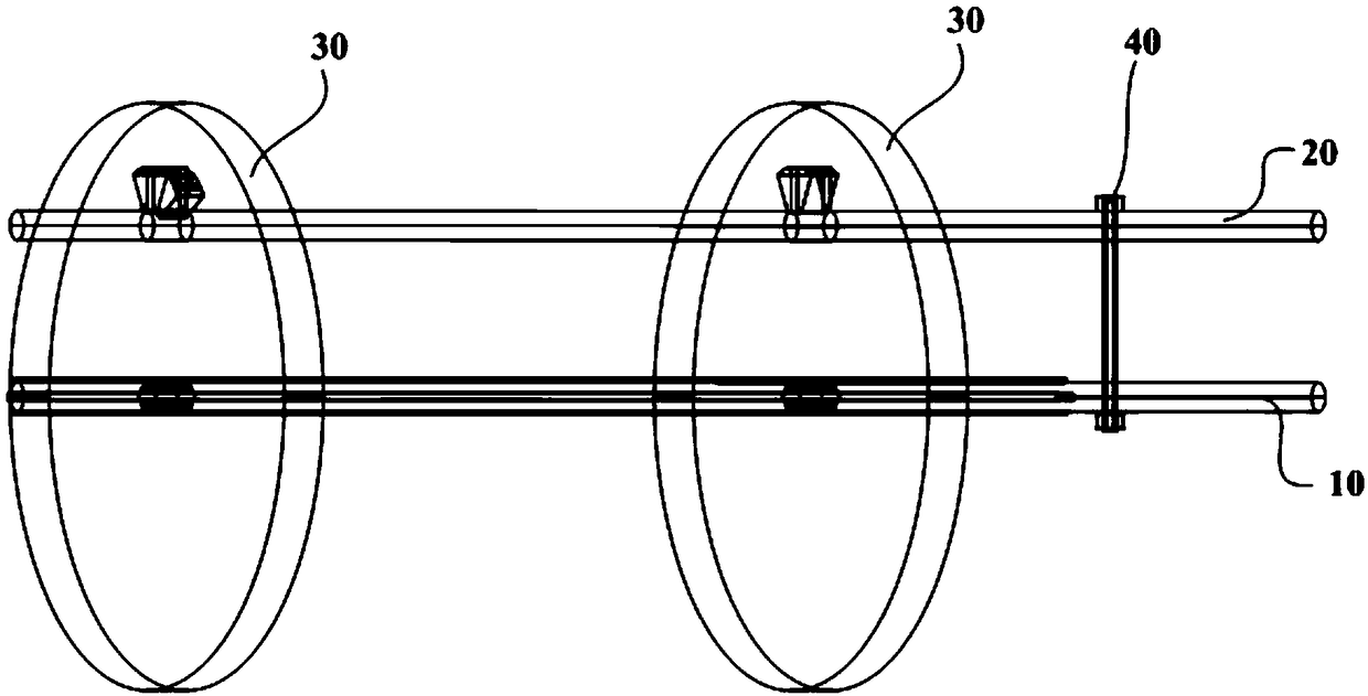
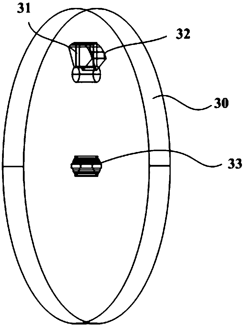
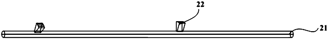
[0046] In order to reduce the operation difficulty of cleaning and maintaining the substrate transfer equipment, and further improve the efficiency of cleaning and maintenance of the substrate transfer equipment, embodiments of the present invention provide a substrate transfer device, a substrate cleaning device and a disassembly method thereof. The following will clearly and completely describe the technical solutions in the embodiments of the present invention with reference to the accompanying drawings in the embodiments of the present invention. Obviously, the described embodiments are only some of the embodiments of the present invention, not all of them. Based on the embodiments of the present invention, all other embodiments obtained by persons of ordinary skill in the art without making creative efforts belong to the protection scope of the present invention.

[0047] like Figure 1 ~ Figure 3 As shown, the embodiment of the present invention provides a substrate tran...


PUM


Abstract

The invention relates to the technical field of substrate conveying and discloses a substrate conveying device, substrate conveying equipment and a detaching method thereof. The substrate conveying device comprises a plurality of substrate conveying units. Each substrate conveying unit comprises a rotating shaft, a fixed shaft, a plurality of rollers arranged on the rotating shaft and the fixed shaft in a sleeving mode and a locking mechanism. The rotating shafts are arranged at the centers of the multiple rollers which can rotate around the rotating shafts and can move in the length directions of the rotating shafts. Each fixed shaft comprises a fixed shaft body and a plurality of positioning protruding blocks protruding out of the fixed shaft body. The position protruding blocks and the rollers are arranged in one to one correspondence. The fixed shafts are arranged between the centers and the edges of the multiple rollers. The rollers are provided with avoiding positions avoiding the positioning protruding blocks and limiting grooves communicating with the avoiding positions. The positioning protruding blocks rotate to the avoiding positions, arranged correspondingly to the positioning protruding blocks, of the rollers, and then can be limited in the limiting grooves communicating with the avoiding positions. The locking structures are used for enabling the rotating shafts and the fixed shafts to keep relative fixing.

Description

technical field [0001] The invention relates to the technical field of substrate transfer, in particular to a substrate transfer device, substrate transfer equipment and a disassembly method thereof. Background technique [0002] At present, in the field of liquid crystal display, the display substrate mainly relies on the substrate conveying device to realize the conveyance on the production line. The substrate transfer device usually includes a plurality of substrate transfer units arranged side by side. Each substrate transfer unit includes a rotating shaft and a plurality of rollers sleeved outside the rotating shaft. The substrate is placed on the rollers. When the rotating shaft rotates to drive the rollers to rotate, the substrate also follows The movement occurs. [0003] If the substrate is damaged during the transfer process, the debris will pollute the substrate transfer device. When using the contaminated substrate transfer device to transfer the substrate, it w...

Claims


Application Information

Patent Timeline
Patent Type & Authority Patents(China)
IPC IPC(8): B65G35/00
CPCB65G35/00
Inventor 李健李晶晶刘浏李朝阳陈巍高亚东任立志
Owner BOE TECH GRP CO LTD
Why Eureka
Try Eureka