Angle cutter realizing smooth cutting and preventing burrs of end side and implementation method of angle cutter

A kind of technology of hair cutting machine and cutting mechanism, which is used in metal processing machinery parts, clamping, supporting and other directions, and can solve the problems of rough grinding of cutting grooves, fuzzing of saw material broken edges, uncontrollable installation accuracy, etc.

Active Publication Date: 2017-07-28
SHENZHEN JINRONGKE TECH CO LTD
View PDF7 Cites 5 Cited by
  • Summary
  • Abstract
  • Description
  • Claims
  • Application Information

AI Technical Summary

Problems solved by technology

[0005] However, due to the installation error in the actual installation, if there is no gap between the saw blade and the cutting groove, the problem of installation error must be solved. The groove is polished rough, which is more likely to cause fluff on the broken edge of the saw material. However, the installation accuracy cannot be controlled, so there is a uniform gap between the saw blade and the cutting groove on the market

Method used


Image

  • Angle cutter realizing smooth cutting and preventing burrs of end side and implementation method of angle cutter
  • Angle cutter realizing smooth cutting and preventing burrs of end side and implementation method of angle cutter
  • Angle cutter realizing smooth cutting and preventing burrs of end side and implementation method of angle cutter

Examples


Embodiment 1

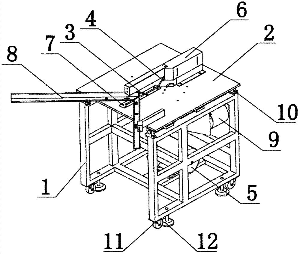
[0020] Embodiment 1: as figure 1 As shown, a cutting flat end edge lint-free chamfering machine and its realization method include a frame 1 on which a board 2 and a cutting mechanism are carried, the cutting mechanism is accommodated in the frame 1, and the platen 2 Arranged on the top of the frame 1, two sets of supporting mechanisms are set on the bottom of the frame 1, one set is four casters 11 set on the four corners of the bottom, and the other set is also four sets of positioning plates set on the four corners of the bottom The fixed support 12.

[0021] The cutting mechanism further includes a cutting wheel 4 and a drive motor 5, the cutting wheel 4 is installed on a rotating shaft, the two ends of the rotating shaft are installed in a pair of bearing seats on the frame 1, and one of the ends of the rotating shaft protrudes A driven pulley is sleeved outside its corresponding bearing seat. The driving motor 5 is located directly below the cutter wheel 4. A driving pu...

Embodiment 2

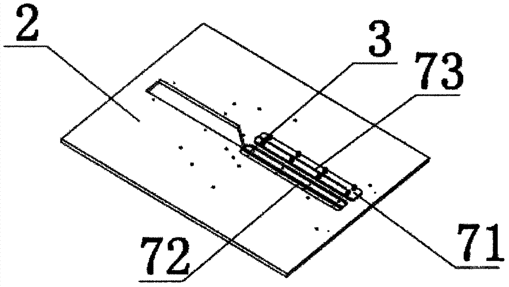
[0031] Embodiment 2: as image 3 As shown, the structure of the end edge lint-free mechanism 7 is also such as: the end of the cutting groove 3 is not arranged with the cutting wheel 4. A step groove 72 with a width greater than its groove width is recessed inwardly, and a brittle inlay is filled in the step groove 72 71 , the exposed end surface of the brittle inlay 71 is flat and flush with the upper end surface of the platen 2 . The fragile inlay 71 is a piece of plastic.

[0032] All the other are with embodiment 1.

[0033] A method for realizing a corner cutting machine that cuts flat ends and lint-free edges. When the corner cutting machine leaves the factory, the platen and the cutting mechanism are immobile and fixed. The cutting wheel passes through one end of the cutting groove, and the other end of the cutting groove penetrates up and down, and Fill with brittle inlays seamlessly and not loose; when the angle cutter is turned on for the first time, the platen and...


PUM


Abstract

The invention discloses an angle cutter realizing smooth cutting and preventing burrs of an end side and an implementation method of the angle cutter. The angle cutter comprises a bedplate; the bedplate is provided with a cutting slot; the cutting slot is used for a cutting knife wheel to pass through and is arranged along a rectilinear direction; inside the cutting slot, one end provided with no cutting knife wheel is filled with a fragile insert; and an exposed end face of the fragile insert is smooth and is flush with the upper end face of the bedplate. The main concept of the angle cutters still starts with elimination of a clearance between the cutting knife wheel and the cutting slot to make sure that a sawed material is always supported and burrs caused by inertial rupture in a cutting process can be prevented, so the first problem to be solved is installation precision; however, the angle cutter disclosed by the invention steers clear of the installation precision problem, the cutting slot and the cutting knife wheel still have the clearance, but the cutting slot is filled with the fragile insert, and the final actual movement direction of the cutting knife wheel is generated by cutting when being started for the first time, so the cutting knife wheel has no clearance with the clearance at the fragile insert.

Description

technical field [0001] The invention relates to the technical field of corner cutting machines, and more specifically relates to a corner cutting machine for cutting flat ends and lint-free edges and a realization method thereof. Background technique [0002] Angle cutting machine, capable of 45-degree bevel or polygon cutting, suitable for cutting and beveling picture frames, photo frames, wooden strips, furniture, plastic strips, aluminum profiles and door frames, and can design polygonal patterns and shapes according to the calculated angle pattern. [0003] Its structure is as described in the patent CN201120381464.3, which includes a motor, a saw blade, a worktable, a slide rail and a fixing device. The fixing device includes a screw and a screw support, and the screw is installed on the screw support. In the seat, the screw support is installed on the workbench, the workbench is installed on the slide rail, the motor is installed on the lower part of the workbench, th...

Claims


Application Information

Patent Timeline
Patent Type & Authority Applications(China)
IPC IPC(8): B23D79/00B23Q3/18
CPCB23D79/00B23Q3/18
Inventor 李楚坚
Owner SHENZHEN JINRONGKE TECH CO LTD
Why Eureka
Try Eureka