
Needle cylinder mechanism of two-sided terry circular knitting machine

A technology of circular knitting machine and double-sided wool, which is used in weft knitting, circular knitting machines with separate action needles, knitting, etc. First-class problems, to avoid the breakage and fluffing of the terry yarn, and the effect of easily falling off

Inactive Publication Date: 2013-05-15
洪荣豪
View PDF1 Cites 0 Cited by
  • Summary
  • Abstract
  • Description
  • Claims
  • Application Information

AI Technical Summary

Problems solved by technology

[0002] Generally, the needle cylinders of known circular knitting machines have the slub slots set in a straight shape, which can only accommodate the insertion of the slugs for telescopic movement. If it is necessary to produce double-sided towel products, there is no loop on the back. Most of the accommodating space will add an auxiliary ring on the needle cylinder, so that there is an appropriate distance from the knitting needle to accommodate the back loop. However, during the knitting process, because there is no support within the appropriate distance, Therefore, it is impossible to make the new terry loops woven by the knitting needles tight, and loosening will occur, which makes the quality of the fabric difficult to control, resulting in the problem of uneven lengths of terry loops. Broken terry yarn, causing damage to the fabric
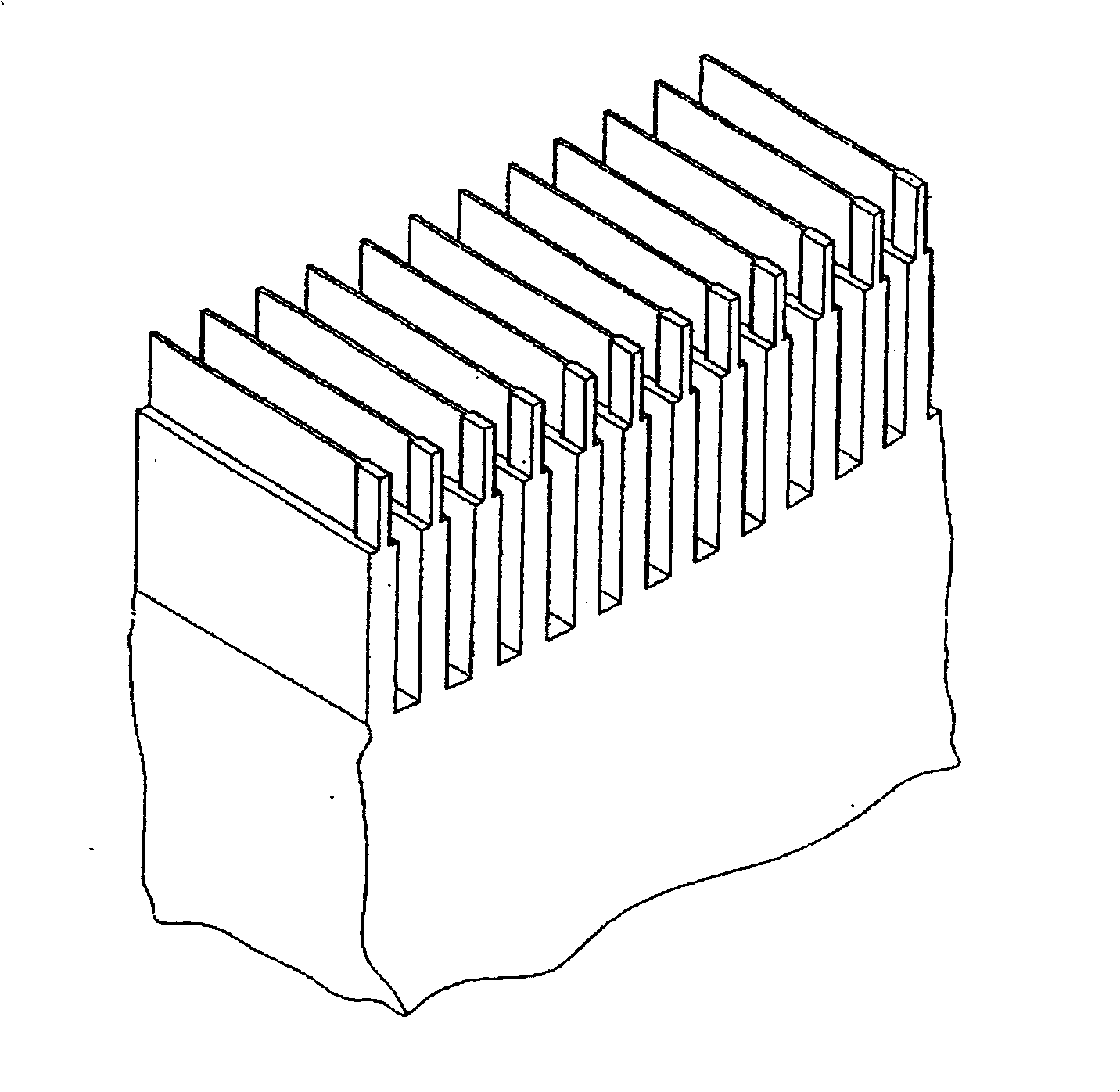
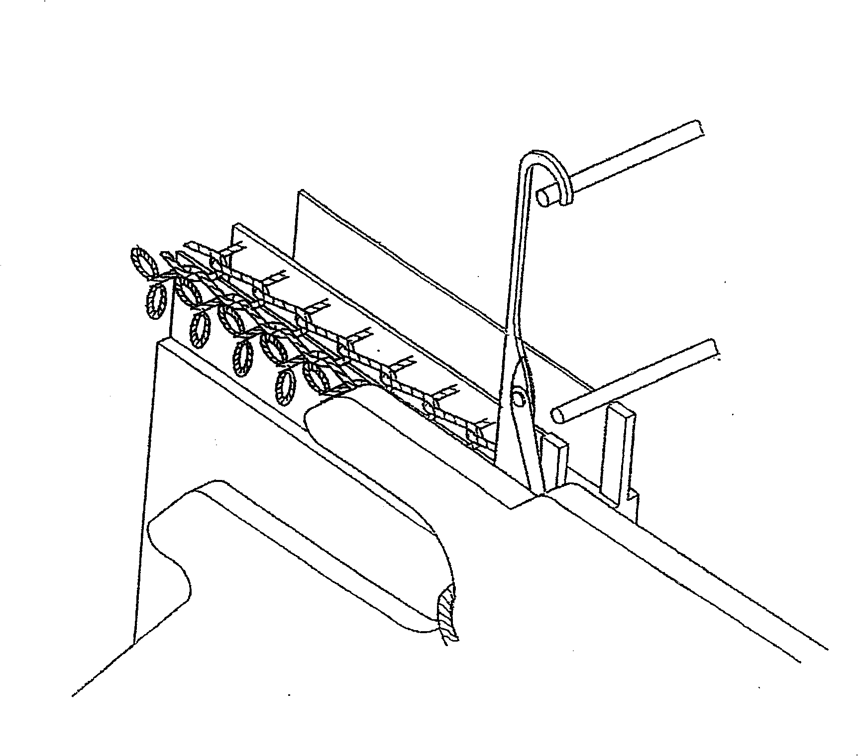
[0003] Therefore, in order to improve the above-mentioned shortcomings, some manufacturers have developed a staged slush groove with a wider upper end and a narrower lower end on the syringe, or thinned the back section of the upper spacer to make the back of the barrel thinner. The upper part of the Duan Shengke slot is wider (see figure 1 , 2 , ZL No. 00265374.5 patent), in order to be able to accommodate the raw gram sheet and the back loop, so that the weaving of the cloth surface is relatively smooth. However, under the operation of the high-speed operation of the machine, the loops on the back are accommodated in a narrow space, which may be squeezed and hindered to some extent, resulting in unsmooth delivery of the cloth, and the raw gram groove in the front section is relatively tight. If the yarn is narrow, it will also cause the yarn to be pushed into the groove of the green sheet, and when the knitting needle hooks the yarn to knit, it will cause the surface hair to be of different lengths, or the terry yarn and the terry yarn that squeeze the surface hair will rub against the wall of the groove and fluff will occur. , so that the quality of the fabric is poor. Moreover, the above-mentioned general needle cylinder structure, the groove bottom of the slug groove is designed to be parallel, and when the yarn is knitting the needle and hooking the yarn to weave the fabric, some cotton dust will be generated to some extent. , the cotton dust will fall and accumulate in the groove and the bottom of the groove. Although the weaving port of the general machine is equipped with an air nozzle to blow off the cotton dust, its effect is limited. When the cotton dust accumulates to a certain extent , it must be stopped and cleaned in good time, otherwise the slug will be worn out or even the slug or the syringe will be damaged, which will relatively reduce the production efficiency and cause losses. Therefore, there are still many shortcomings that need to be improved

Method used


Image

  • Needle cylinder mechanism of two-sided terry circular knitting machine
  • Needle cylinder mechanism of two-sided terry circular knitting machine
  • Needle cylinder mechanism of two-sided terry circular knitting machine

Examples


Embodiment Construction

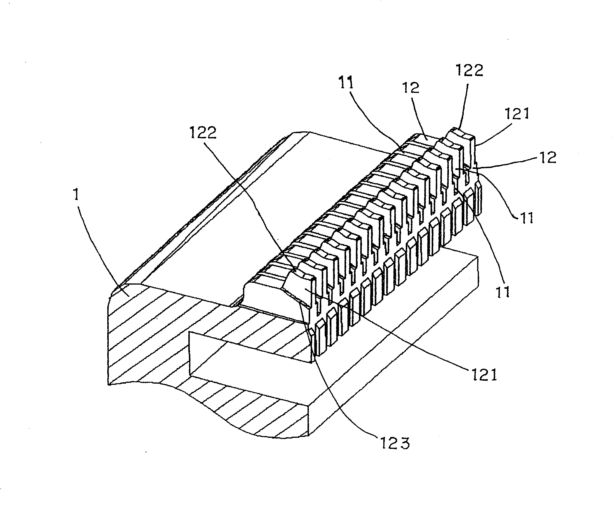
[0021] See image 3 , Figure 4 , The present invention is mainly provided at the upper end of the front section of the spacer 12 between the syringe 1 sinogram slot 11, a protrusion 121 that is higher and thinner than the spacer, so that the upper end of the sinogram slot 11 of the syringe 1 The shape is wide and narrow at the lower end, while the sinker slot 11 in the rear section continues the sinker slot 11 at the lower end of the front section. The lower end of the syringe 1 is narrower than the slot width of the sinker slot 11 and can only accommodate The gram piece 2 enters, the upper edge of the rear end of the protrusion 121 is a flange 122 protruding upward along the protrusion 121, and at the bottom of the protrusion 121, a slope 123 extending downward and forward is provided.

[0022] By means of the aforementioned structure and shape of the needle cylinder 1, when knitting materials, the narrower sinker slot 11 at the lower end of the needle cylinder 1 can make the s...


PUM


Abstract

The invention discloses a needle cylinder mechanism of a double-side terry circular knitting machine. The upper end of a front space part section in a needle cylinder sinker slot is provided with a relative high and thin projection part, a higher flange is arranged at the rear end upper edge of the projection part, and the bottom of the projection part is an inclined plane extending downwards andforwards; the slot width of a narrower sinker slot at the lower end of the needle cylinder can only accommodate access of the sinker; the projection part at the front end upper edge of the space partis thin so as to cause the slot forming the front sinker section to have a wider upper end and a narrower lower end. The needle cylinder can help cause the terry at the face side and the back side ofknitted fabrics to have the same length, prevent broken terry yarn and fluffiness, cause cotton flock produced in the knitting operation to easily drop, and produce no stockpiling and blockage.

Description

Technical field [0001] The invention relates to a needle cylinder mechanism of a double-sided terry circular knitting machine. Background technique [0002] Generally, the needle cylinders of circular knitting machines have a straight shape in their sinkers, which can only accommodate the insertion of the sinkers for expansion and contraction. For the production of double-sided towels, there is no back loop. In most cases, an auxiliary loop is added to the needle cylinder to allow an appropriate distance between the needle and the knitting needle to accommodate the back loop. However, during the knitting process, there is no support in this appropriate distance. Therefore, it is impossible to make the new loops woven by the needle hooks tight, which will cause looseness, which makes the quality of the fabric difficult to control, resulting in the problem of different loop lengths, even when the satin sheet is stretched forward, it may be hooked. The terry yarn is broken and the ...

Claims


Application Information

Patent Timeline
Patent Type & Authority Patents(China)
IPC IPC(8): D04B15/14D04B9/10
Inventor 洪荣豪
Owner 洪荣豪
Learn More