An air supplying device

A technology of air supply device and air supply part, which is applied in pump device, pump control, non-variable-capacity pump, etc., can solve the problem that users cannot intuitively understand the scope of air supply, and achieve the effect of easy understanding

Active Publication Date: 2017-07-28
TWINBIRD CORP
View PDF20 Cites 3 Cited by
  • Summary
  • Abstract
  • Description
  • Claims
  • Application Information

AI Technical Summary

Problems solved by technology

[0007] However, in such an air blower, the swing range of the air blower can be switched to other angles by using the push-button switch arranged on the operation panel. Understand the range of air you want

Method used


Image

  • An air supplying device
  • An air supplying device
  • An air supplying device

Examples


Embodiment Construction

[0057] Below, based on Figure 1 to Figure 11 Embodiments of the present invention will be described. In addition, the embodiment described below does not limit the content of the present invention described in the claims. In addition, all of the configurations to be described below are not limited to essential requirements of the present invention.

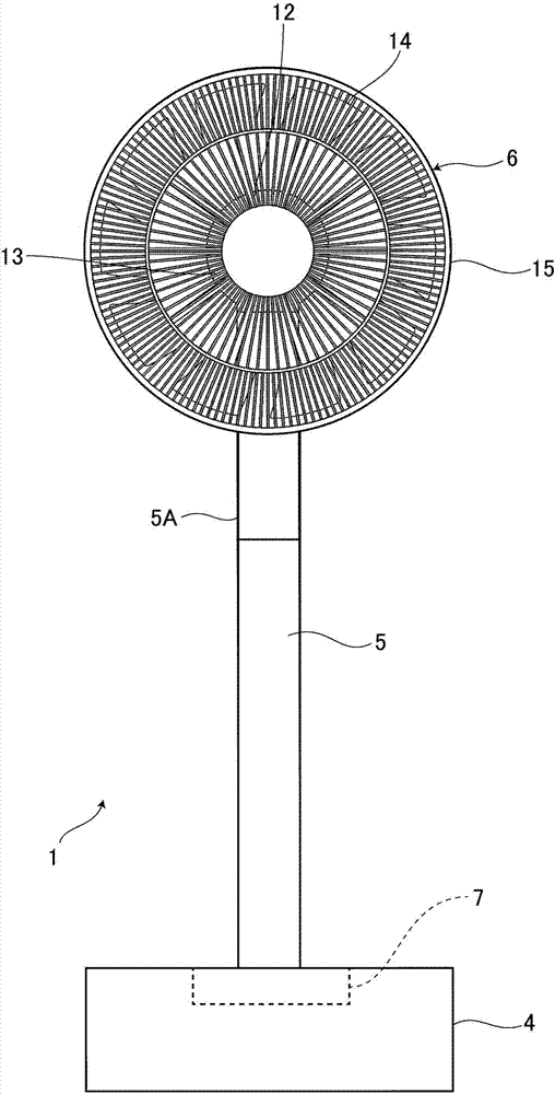
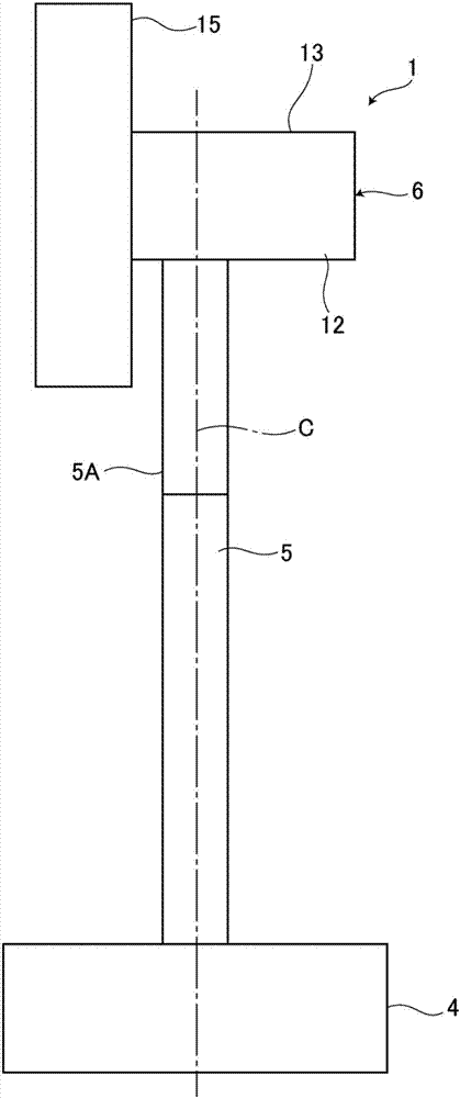
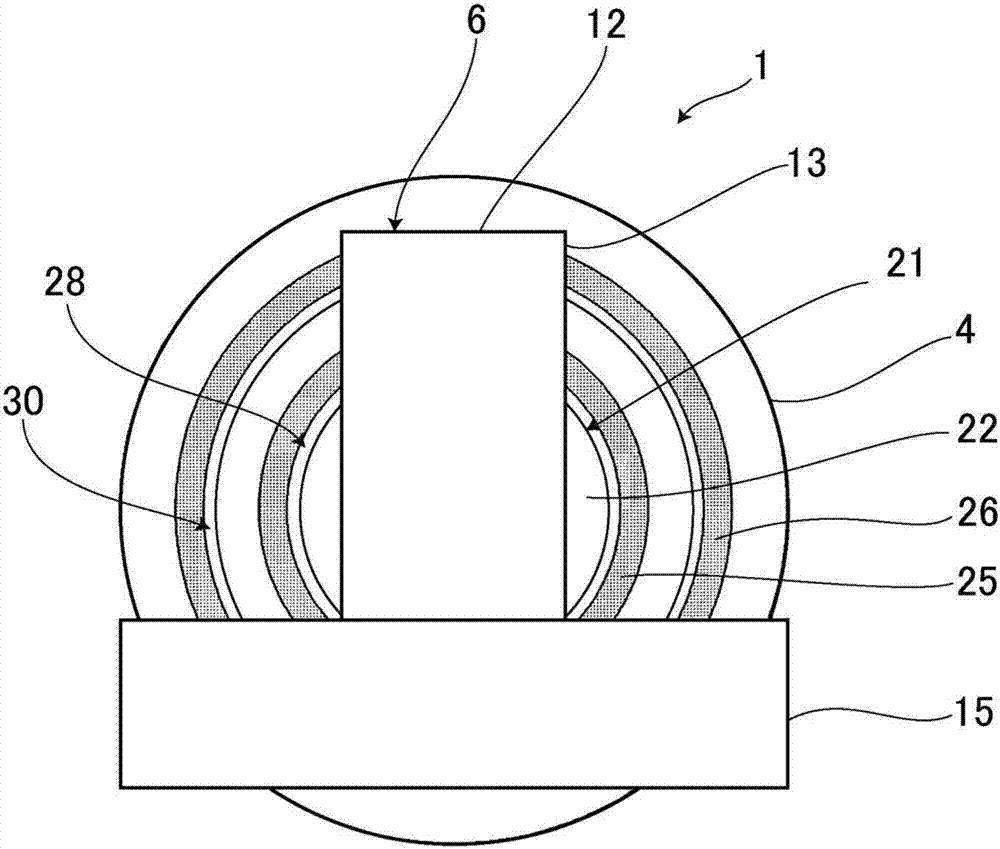
[0058] First, based on Figure 1 to Figure 4 The whole structure of the fan used as an air blower is demonstrated. 1 is a fan main body with air supply function. And, using this fan main body 1 and the remote controller 2 described later (refer to Image 6 ) to constitute the fan of this embodiment. The fan main body 1 serving as the main body of the air blower is configured to include: a base 4 placed on a floor (not shown); a support 5 erected upward from the center of the base 4 ; and an upper end of the support 5 . and a moving mechanism 7 for imparting a driving force for one-way rotation or two-way rotation of the sup...


PUM


Abstract

An air supplying device capable of easily, intuitively understanding and specifying a desired air supplying range in a movable range of an air supplying part is provided. The device is provided with a base (4) supported on the floor, a pillar (5) disposed on the base (4), the air supplying part (6) disposed at the upper end of the pillar (5), and a moving mechanism (7) allowing the air supplying part (6) to relatively rotate or rotate relative to the base (4) at the horizontal direction. On the upper surface of the base (4), a second touch sensor (26) specifying the air supplying direction of the air supplying part (6) in an annular or arc-like manner so that the lower end of the pillar (5) is surrounded.

Description

technical field [0001] The present invention relates to air supply devices such as fans and circulators. Background technique [0002] In the past, as such an air blowing device, a known fan has a base as a base placed on the floor, a pillar portion provided above the base, and an upper end portion of the pillar and has a fan for blowing air. The air supply part of the fan blade, and the left and right swing head mechanism as a moving mechanism that makes the air supply part swing in the left and right horizontal directions are connected to the power supply by operating the switch on the operation panel on the upper surface of the base. ON / OFF switching, ON / OFF switching of the left and right head swing mode, selection of the head swing angle, and switching of the air volume level from the blower (for example, refer to Patent Document 1). [0003] In addition, another patent document 2 discloses a fan including: a fan main body having a base, a pillar, and a blower; The li...

Claims


Application Information

Patent Timeline
Patent Type & Authority Applications(China)
IPC IPC(8): F04D25/10F04D27/00
CPCF04D25/105F04D27/004F04D27/007F04D27/008
Inventor 我妻瞳船山秀树狩山晃辅
Owner TWINBIRD CORP
Why Eureka
Try Eureka