

Controller, control method for controller, and computer readable recording medium
A control device and control method technology, applied in the direction of program control, calculation, program control, etc. in the sequence/logic controller, can solve the problem that the recorded content is difficult for users to understand, etc.
- Summary
- Abstract
- Description
- Claims
- Application Information
AI Technical Summary
Problems solved by technology
Method used
Image

Examples
Embodiment approach 1
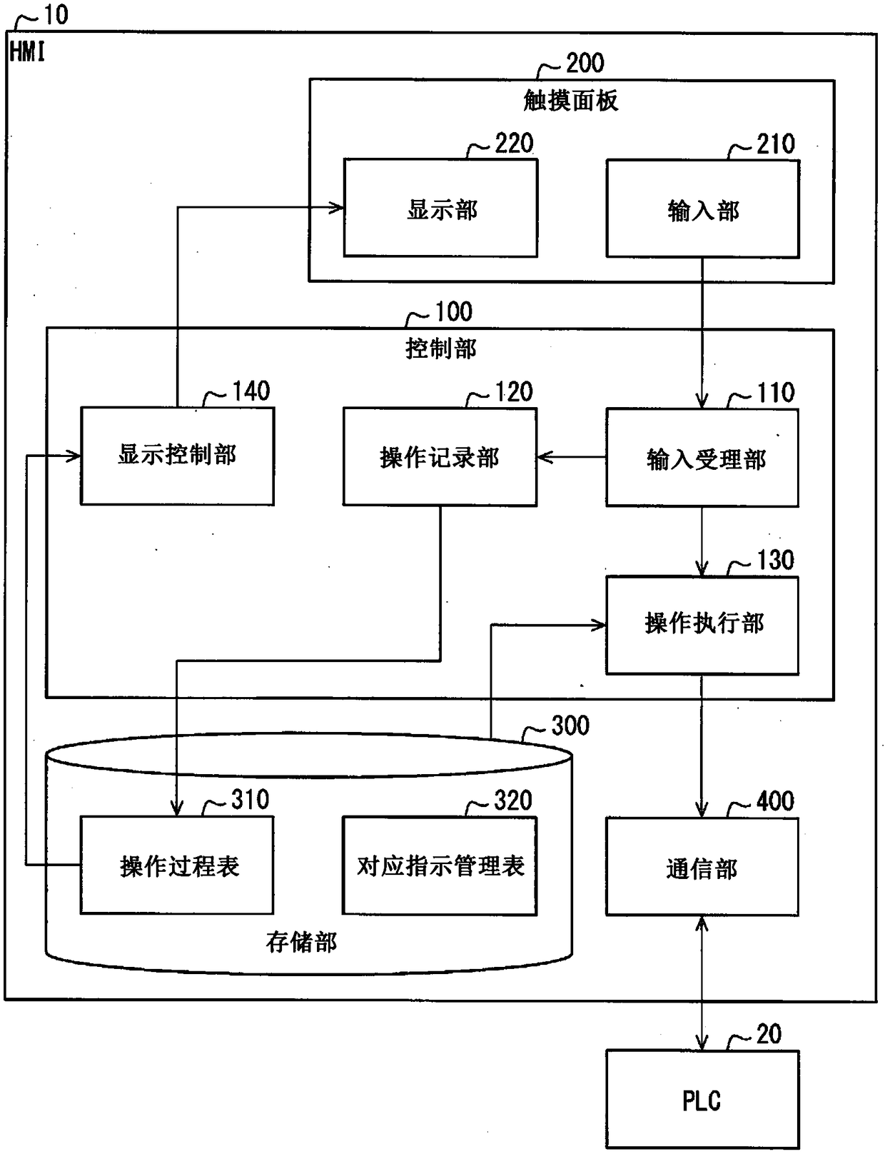
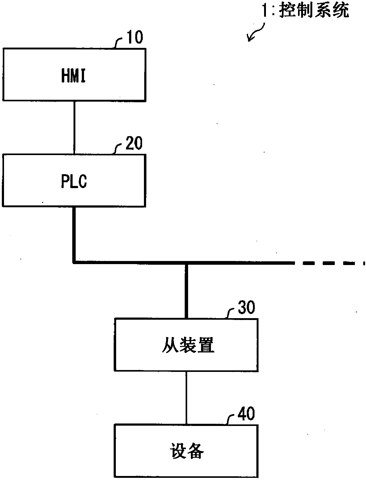
[0054] Below, based on Figure 1 to Figure 7 Embodiment 1 of the present invention will be described in detail. The same symbols are attached to the same or corresponding parts in the drawings, and the description thereof will not be repeated. In order to facilitate the understanding of the HMI 10 (controller) which is an embodiment of the present invention, first, use figure 2 An overview of the control system 1 including the HMI 10 will be described. In addition, although the example in which the control apparatus of one aspect of this invention is HMI is demonstrated below, the control apparatus of one aspect of this invention is not necessarily HMI.
[0055] (Outline of the control system of Embodiment 1)
[0056] figure 2 It is a figure which shows the outline|summary of the control system 1. Such as figure 2 As shown, the control system 1 is a master-slave control system including: a PLC (Programmable Logic Controller, Programmable Logic Controller) 20 as a mast...
Embodiment approach 2
[0133] based on Figure 8 to Figure 18 Other embodiments of the present invention will be described below. In addition, for convenience of description, members having the same functions as those described in the above-mentioned embodiments are denoted by the same reference numerals and their descriptions are omitted.
[0134] (About HMI)
[0135] Figure 8 It is a block diagram showing the configuration of main parts of HMI 11 according to Embodiment 2 of the present invention. Figure 8 The control unit 101 of the illustrated HMI 11 except figure 1 The control unit 100 of the illustrated HMI 10 includes a status acquisition unit 150 and a notification unit 160 in addition to the functional blocks included. About the structure other than the status acquisition part 150 and the notification part 160, HMI11 is the same as HMI10.
[0136] The status acquisition unit 150 acquires information (status information) related to the status of at least one of the PLC 20 , the slave ...
Embodiment approach 3
[0226] based on Figure 19 and Figure 20Other embodiments of the present invention will be described below. In addition, for convenience of description, members having the same functions as those described in the above-mentioned embodiments are denoted by the same reference numerals and their descriptions are omitted. In order to facilitate the understanding of the HMI 12 (control device) of one embodiment of the present invention, first, use Figure 20 The outline of the control system 3 including the HMI 12 will be described.
[0227] (Outline of the control system of Embodiment 3)
[0228] Figure 20 It is a figure which shows the outline|summary of the control system 3. Such as Figure 20 As shown, in the control system 3, several HMI12 (1)-(3) are mutually connected via a network. In addition, in the following description, when it is not necessary to distinguish some HMI12 (1)-(3), several HMI12 (1)-(3) is abbreviated as "HMI12", respectively. Such as Figure 20...
PUM
 Abstract
Description
Claims
Application Information