Airflow controlled magnetic valve suitable for outdoor used

A technology of airflow control and solenoid valve, which is applied in the direction of valve lift, valve details, valve device, etc., which can solve the problem of affecting the effect of solenoid valve air supply, discharge and energy saving, affecting the driving force and sensitivity of solenoid valve, and the inconvenience of solenoid valve installation instructions lamps and other issues, to achieve the effect of easy mass production, compact structure and good sealing

Inactive Publication Date: 2008-02-13
温伟光
View PDF6 Cites 1 Cited by
  • Summary
  • Abstract
  • Description
  • Claims
  • Application Information

AI Technical Summary

Problems solved by technology

At present, the driving force, sensitivity and reliability of the solenoid valve originally prepared by the control device are not ideal enough.
For example, when a motorcycle or a car is running at a higher speed, due to the increase of the driving current of the solenoid valve, the working temperature in the valve body rises. At present, most of them adopt the structure of a plastic shell with a U-shaped soft iron frame, and they are still installed. Rubber sleeves should be put on, so that the working parts in the valve body cannot effectively dissipate heat and cool down, which will greatly affect the driving force and sensitivity of the solenoid valve, and will also affect the air replenishment effect of the solenoid valve, that is, the emission and energy saving effect of motor vehicles.
In addition, because the original electromagnetic valve is not easy to install the indicator light, the driver of the motor vehicle is not easy to intuitively understand whether the electromagnetic valve is working normally.
Moreover, when encountering harsh external environments and weather conditions, the reliability of the existing solenoid valve is reduced, and its structure is poorly sealed, so it cannot be well protected against moisture and water.

Method used


Image

  • Airflow controlled magnetic valve suitable for outdoor used
  • Airflow controlled magnetic valve suitable for outdoor used
  • Airflow controlled magnetic valve suitable for outdoor used

Examples


Embodiment Construction

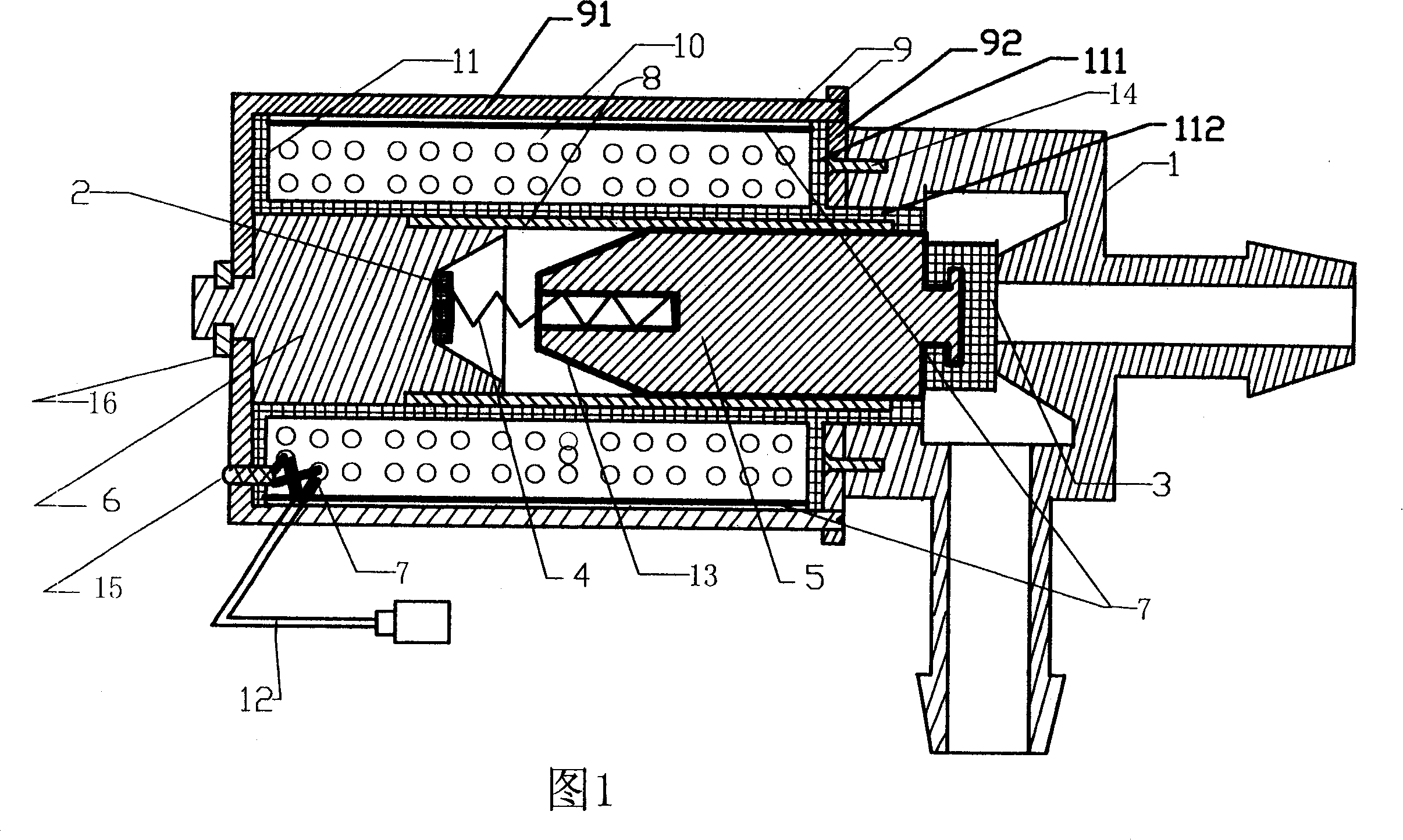
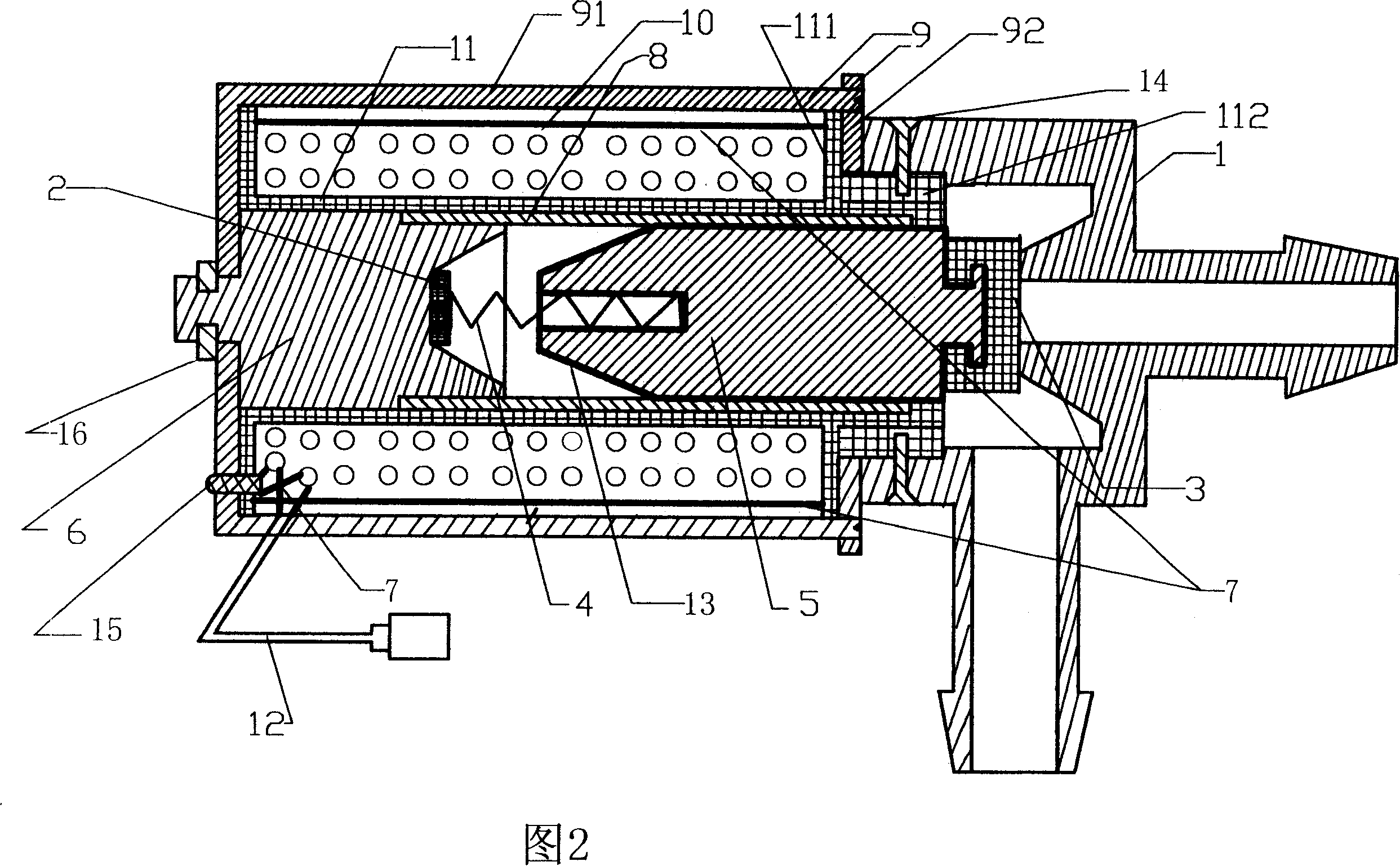
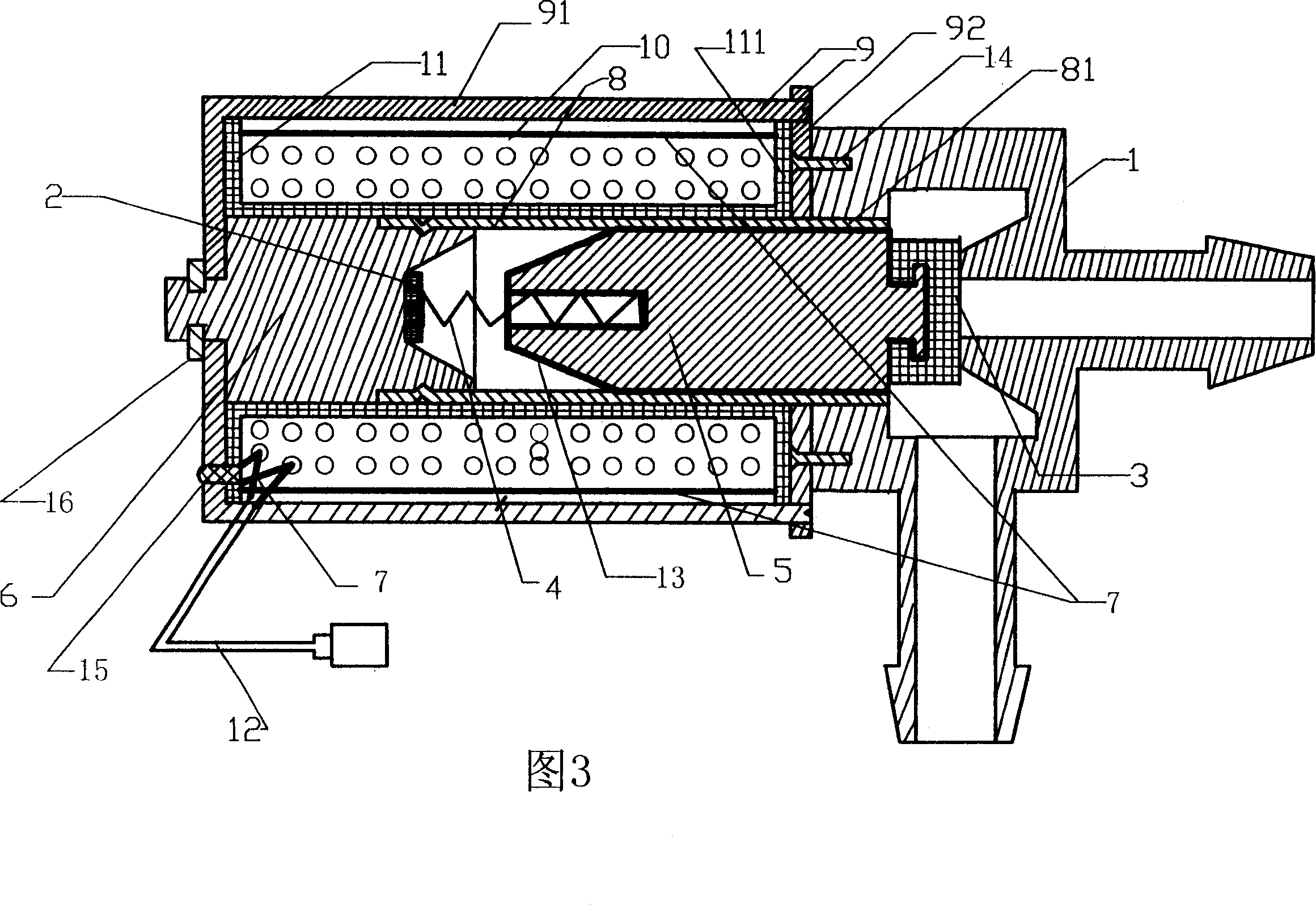
[0018] As shown in Fig. 1-6, the present invention includes valve seat 1 and electromagnetic drive device with air inlet and air outlet, and described electromagnetic drive device comprises: a soft iron sleeve 9, and it is formed by a U-shaped Frame 91 and a sealing baffle 92 constitute, the U-shaped frame 91 is sleeved on the outermost part of the electromagnetic drive device, and the two ends of the U-shaped frame 91 are connected with the sealing baffle 92; The wire 12 is connected and wound on the outside of the wire bag frame 11, and is built in the cavity between the soft iron set 9 and the wire bag frame 11; In the shaped frame 91; a certain iron core 6, which is inserted and fixed at one end of the hollow inner cavity axis of the wire bag skeleton 11; a moving iron core 5, whose end facing the valve seat 1 is connected with a sealing ring 3, and which is inserted into the wire The other end of the hollow inner cavity axis of the package skeleton 11; after assembly, the...


PUM


Abstract

The invention relates to an outdoor air flow control electromagnetic valve, comprising valve seat, a soft iron matched set, several groups of drive coils, a fixed iron core and a moving iron core, and after assembling, a seal baffle in the soft iron matched set is jacketed on the upper spacing baffle of a coil frame, the valve seat is fixedly jacketed on the upper seal baffle of the coil frame, a reset spring is installed between the moving and fixed iron cores; the drive coil and signal input line connection part are jacketed with heat-shrink tubes, and the periphery of the drive coil is also jacketed with heat-shrink tube. The invention largely improves heat radiating function and rain- and damp- proofing function. And the electromagnetic valve can be widely applied to motor vehicles and other outdoor devices.

Description

technical field [0001] The invention relates to the technical field of an electronically controlled air supply device for a motor vehicle engine, in particular to an air flow control solenoid valve suitable for outdoor applications. Background technique [0002] In the electronically controlled energy-saving purification device (or electronic air supply device) of automobiles and motorcycles, the solenoid valve is the core executive component. The controller ECU in the control device outputs control signals to the solenoid valve to control the solenoid valve to open and close. The duty cycle of the time, thereby realizing the supplement and regulation of the air flow into the engine. That is to say, the concentration of the mixed gas provided by the car or motorcycle is controlled so that the engine can achieve good combustion, thus effectively reducing fuel consumption and reducing harmful emissions. As the control device changes with the operation of the engine, it sends ...

Claims


Application Information

Patent Timeline
Patent Type & Authority Patents(China)
IPC IPC(8): F16K1/00F16K31/06
Inventor 温伟光
Owner 温伟光
Why Eureka
Try Eureka